Nowhere Spaces (Room/Scene) Basics
Table of Contents
In Nowhere, scenes are called Spaces. While the word may be different, they are functionally the same as ‘rooms’, ‘levels’, ‘maps’ or whatever categorical synonym is used to describe ‘the space in which Users interact‘. With that said, to make a Nowhere compatible scenes using Blender, a few basic requirements need to be followed, namely, how the mesh itself is set up, scene collision, and the core entities/interactive elements necessary to create a functional space.
Download: KatsBits – Nowhere Examples (c. 650KB | *.blend, *.gltf, *.jpg, *.png). Open *.blend in Blender 3.6 LTS and above only.
Design note: the following assumes a scene is ready and available for Nowhere prep in Blender. A basic understanding of Blender will also be useful to make the most from the below information.
Room/Scene Basics
Generally speaking, the basic components of a room for Nowhere include;
- a mesh that describes the structure of a Space [1].
- at least one material that defines visual elements of the scene [2].
- a collision hull that defines the physical limitations of the room [3].
- and a set of interactive elements that establish the various ‘user interactive’ aspects of the experience [4].
Design note: Nowhere uses its own camera system so Blenders default Camera entity is not needed.
Aside from the above considerations there are no general artistic, creative or expressive limitations as to what a given space might look like, or how they might function, notwithstanding such functionality being based on the the capabilities of the available entity objects.
Design note: the primary rule governing content creation for the metaverse is “optimise, optimise, and optimise some more“. In practice this means Nowhere is essentially a user-customisable online content delivery system so the asset creation process is loosely governed by the same set of rules that define online interactive spaces generally, that they;
- use as few assets as possible to minimise data/bandwidth throughput.
- be as heavily optimised as is practicable to reduce rendering throughput.
In other words, a mesh that’s 50k is far better than 500k for a space so long as the overall integrity of the scene isn’t compromised. And similarly a 512 x 512 pixel image is more efficient than a 2048 x 2048 where such reductions don’t correspondingly reduce the quality of the visual experience.
The other rule is “just because it can be done, doesn’t mean it should“!
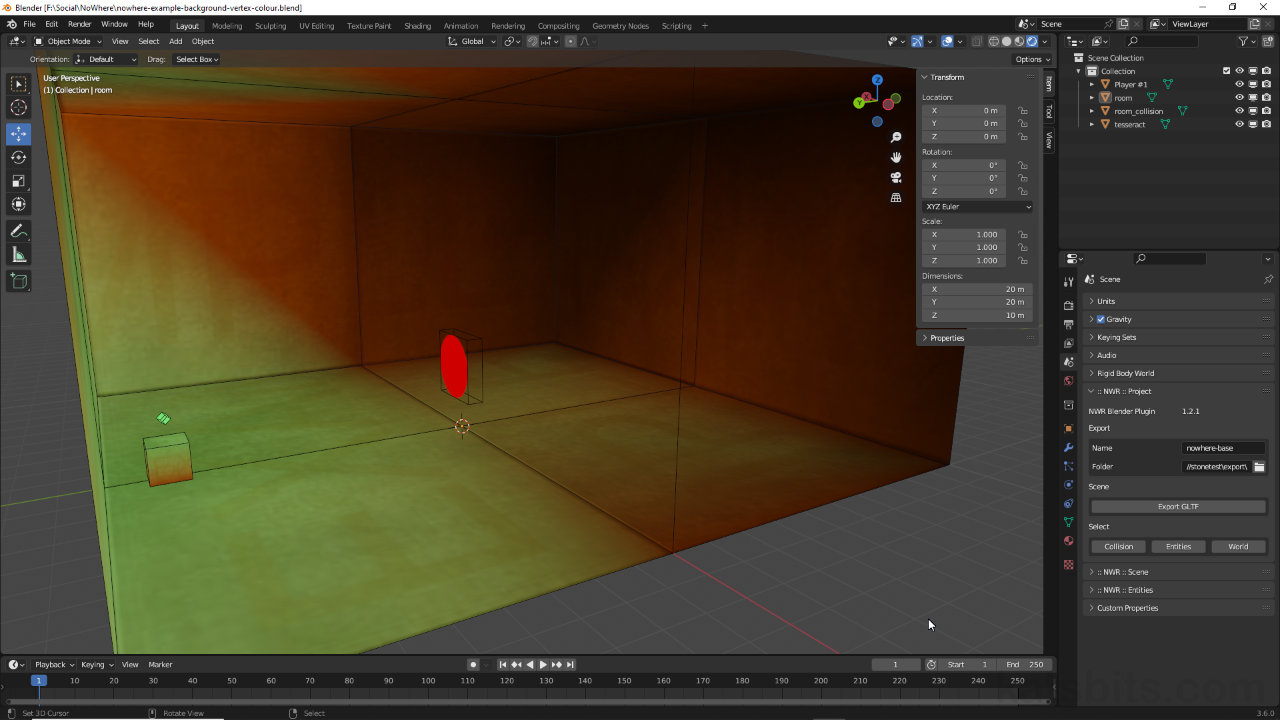
With this in mind a simple scene is shown below, essentially a 20 x 20 x 10 unit box illuminated by a single dynamic (aka ‘real-time’) light source, a colour tinted Point light, and a single Player locator. The scene also includes a collision hull that, for the purposes of production, is displayed as a wireframe outline so as not to interfere with ongoing development. Both visible mesh and collision hull (see “Collision Hull” below) are as low resolution as possible, using only those polygons necessary to describe the shape of the scene. Similarly the feature item, a small plinth, is also minimally structured. Both meshes are also assigned materials but only the game mesh is UV Unwrapped and UV Mapped with images (see “Material Setup” below).
Important: Nowhere uses the same core Units of Measurement as Blender, i.e. 1 Meter/Unit in Blender = 1 metre/unit in Nowhere. For scaling, a Player spawn point can be placed (2 x 2 x 0.5 metres).
There are two significant caveats to using the Player entity for scaling purposes in Blender;
- if a Player entity spawn-spot is placed flush with a surface [i] in Blender the avatar will typically appear one metre above that surface in Nowhere [ii]. Adjustments to compensate may be necessary.
- although a spawn-point may be specifically positioned in a scene, the avatar does not consistently appear in place when a Space loads into Nowhere, or the user loads into that same Space – this cannot be controlled or compensated for.
The Player entity doesn’t always appear where it’s placed in a scene [i] so may need to be compensated for [ii]


A basic scene in Blender comprising a mesh [1], a material [2], a corresponding collision hull [3] (not visible), and a player spawn entity [4]. The scene is lit using an optional (colour tinted) Point light.

The same scene with component break down; mesh [1], material [2] assigned to the mesh, the collision hull [3] assigned a simple red material and placed to one side for clarity in Blender (not visible in Nowhere), and the player spawn point [4].
Collision Hull Setup
Collision in Nowhere is a surface property so does not specifically comport to the ‘convex/concave‘ rule typical of volume based collision that require solid, closed shapes. This affords greater flexibility and means collision hulls are better able to describe more complex shapes and forms. With that said, collision meshes;
- should be as low resolution as possible.
- only need correspondence to major surfaces of the game mesh.
- do not need to be UV unwrapped or mapped, nor assigned any materials.
By way of example, shown below both in-game and collision meshes are the same, largely as a consequence of the game mesh being low enough resolution its structure can double up as the collision hull. In other words, in this situation collision is just a duplicate of the game mesh absent UV mapping and/or material assignments. This might not always be the case so collision would then be structured generally to accommodate major features as best as practicable while preventing camera or player clipping through surfaces. This can be done manually editing the mesh or using the Decimate modifier depending on the context.
Design note: aside from essentially making a Space seem solid, collision should be set up to minimise camera and/or player ‘clipping’ (pass through) surfaces and/or see into the void. While the latter isn’t necessarily an issue in of itself, the former can create gaps and holes in collision that players can fall through.

Game mesh (image: left) is a textured box. Collision (image: right), shown materialled in red for clarity, is a duplicate of the game mesh…

… but could be reduced further if needed (image: right) by removing a few edge loops.
Material Setup
Nowhere understands Blenders core material system so most basic assignments will comprise an Image Texture node linked to the default Principled BSDF/Material Output group. In Shading Workspace (or the Shading Node Editor) this just means dropping in a Image Texture node [5], associating an external bitmap with it [6], then linking that node’s Color output to the Base Color input of Principled BSDF. In Nowhere this then displays the bitmap image or colour associated with the Image Texture node. For this approach to work correctly in Nowhere however, the scene needs a light source. The alternative to this is to use a Background node material (see “Scene Lighting” below).
Important: max image size is 2048 x 2048 pixels.
Design note: for basic materials, so long as Principled BSDF forms the core element of the node tree, Nowhere understands the following surface properties/effects;
- Diffuse (Base Color).
- Metallic.
- Specular.
- Roughness.
- Emission.
- Alpha.
They can be expressed as;
- uniform input values directly within Principled BSDF, i.e. 0.000 » 1.000 [iii].
- variables defined by grey-scale images loaded into Image Texture nodes [iv].
- or a combination of the two – one property being an input value, another an image.
Material properties can be input as values [iii] directly in Principled BSDF or linked image data [iv] – the former is uniform the latter variable.


Nowhere understands Blenders material system so an Image Texture [5] node, referencing an external bitmap [6] and linked to Principled BSDF, will display that image in Nowhere.
Scene Lighting
There are two ways to generally illuminate Spaces in Nowhere;
- dynamic (real-time) lights.
- ‘self-illuminating’ materials.
Dynamic (real-time) Lights
Dynamic lights in Nowhere are based on Blenders Point, Sun and Spot lights (Area not supported), and behave much the same in Nowhere as they do in Blender. In other words once a Light object has been placed in a scene [7], in Object Data Properties [8] the entity’s options can then be changed, primarily Color and Power [9] – Color sets the tone, colour or saturation of a light, Power defines it’s brightness or intensity.
Design note: although Color is primarily used to define a lights colour, it can also be used to change a lights perceived brightness by ‘dimming’ the colour attribute towards black – a 1000 Watt light can be effectively turned off or disabled simply by colouring it ‘black’.
Important: there are currently a couple of limitations when using dynamic lights in Nowhere;
- dynamic lights are limited to four (4) per scene.
- dynamic (cast) shadows are not fully supported.

Dynamic lights in Nowhere are translated from Blenders default lighting system, and can be Point, Sun or Spot lights [7], generally adjusted in Object Data Properties [8] for Color and Power (brightness) [9].
Self-Illuminating Materials
Self-illumination in Nowhere relates to materials that don’t react to other sources of light or illumination, they ‘self illuminate’. The effect of this, is for a Space to appear lit without there actually being any active light sources in the room, light entities or otherwise.
Design note: ‘self-illumination’ is a colloquialism for ‘static’ or ‘baked’ lighting, and is generally used because lighting, as a ‘look’ or visual feel of a scene, can be ‘fixed’ without the expense of shading and shadows having to be calculated and cast in real time.
Generally speaking lighting rooms to be self-illuminating can be done by setting a material to;
- ’emit’ light.
- be ‘full-bright’.
Emission (Image & Principled BSDF)
When setting up a material to emit light, two options can be used; Emission and Emission Strength [10], both available towards the bottom of Principled BSDF. Emission is the colour emitted and defaults to white. Emission Strength is the brightness or intensity and defaults to 1.000. If both defaults are used the room will appear over-bright and blown-out because ‘white’ essentially multiples the brightness value. To fix this one and/or/both the other needs to be changed; reducing Emission Strength, e.g. from 1.000 to 0.050, and/or/both darkening the Emission colour, e.g. from RGB 1.000 to 0.010 [11].
Important: materials set to emit light in this context, the self-illumination of world textures, generally need to be used in conjunction with a light source where it behaves similar to ambient light or fill light, i.e. lighting that lightens shadows so they’re not pitch-black. Without a source textures will wash out at (levels would need to be elevated to compensate for lack of light source which will wash-out the scene in Nowhere).
For world textures that use Emission, they’ll generally need to be used in conjunction with a light source where the effect essentially behaves akin to ambient light.

Design note: values will vary depending on the desired effect and images used – light colours will generally need lower colour/value pairings than darker colours.

Self-illuminating materials can be set up using Emission (colour) and Emission Strength (intensity) [10] so textures appear uniformly lit in Nowhere as they are in Blender [11].
Changing input values directly within Principled BSDF however, uniformly flattens the effect, there is no tonal or colour variation, darker or lighter patches of illumination. To address this, and make the resulting perceived illumination reflect the image mapped to the object [12], the Color output from the Image Texture node can be secondarily linked to the Emission input of Principled BSDF [13]. In other words, the image associated with the Image Texture node is providing colour input information for both Base Color (Diffuse) and Emission.

The image associated with the material can connected to the Emission input of Principled BSDF [13], which then provides a more variable emission effect in Nowhere.

The different set ups for self-illumination using uniform Emission values [10] vs. connecting the Image Texture [13].
Background Node
Where Emission acts as an ambient fill light, to make a material ‘full bright’ and effectively lit ‘correctly’ in Nowhere so it doesn’t react at all to scene lighting – images appear as they are when displayed in Blenders Material Preview display mode – materials have to be set up in a slightly different way. Instead of using a Principle BSDF based grouping, materials should be set to use a Background node grouping.
Important: when creating spaces for Nowhere in Blender, Background node based materials should be considered the primary way scenes are ‘lit’ for proper display in Nowhere. In other words, in Blender, Nowhere Spaces should not contain, or be illuminated by, any type of light entity or light source (which will need to be deleted prior to export), and should instead be textured and built such that shading and shadows are ‘baked‘ to images that are then mapped as necessary to meshes (the world). Or alternatively make use of Vertex Color (see “Vertex Color” below).
In Shading workspace have Material Properties accessible and the material to be changed highlighted. In the properties panel click the Surface input field [14] (defaults to displaying Principled BSDF), and from the list click Background [15]. In the Shader Editor this will swap Principled BSDF with a Background node [16] and the mesh assigned the active material will render white. Drop in an Image Texture [17] node and load in the corresponding image that’s supposed to appear on the mesh. Link this nodes Color output to the Color [18] input of the Background node. The mesh will then appear textured, and ‘full bright’ or fully self-illuminated.

The best type of scene illumination for Nowhere is to remove any light sources and swap the Principled BSDF [14] node for a Background [14] node in Material Properties.


The Background [16] node is linked by an Image Texture node [17] that should then be connected Color output to Color input (image-top), which then renders the associated image ‘full-bright’ (image-bottom).
Vertex Colours
Preference in Nowhere is for Spaces to be lit using self-illumination rather than real-time dynamic lighting. As a consequence scenes can appear quite flat, especially where colouring is used alongside tiled texturing. There are two ways this limitation can generally be addressed, either/or/both;
- vertex colours
- baked textures
Of the two approaches, vertex colours are by far more efficient and cheaper than baked images as it allows for the use of tiled textures, which in-turn keep overheads to a minimum and allows for a (relatively) speedy end-user experience.
Design note: due to the low polygon nature of scenes in Nowhere, effective use of vertex colour may mean additional structure having to be added [v] to compensate for the way colour bleeds along edges – elements may appear to float or not be properly ‘grounded’ in a scene because colour doesn’t bleed or flow to neighbouring elements.
For vertex colouring to be effective meshes need to be structured to take the effect into account. In other words additional vertices, edges or faces [v] may need to be placed for shading and shadows to ‘sit’ correctly in a scene.

To paint vertex colours, select the mesh to be painted then switch interaction mode to to Vertex Paint [19]. To see what’s being painted change display mode to Solid [20], use the tools to change colour and/or other aspects of the ‘brush’ [21], and then click-drag the mouse cursor across mesh vertices to ‘paint’ colour.

Switch mode to Vertex Paint [19], and to see the colours painted to the mesh, display mode to Solid [20]. The selected mesh can then be shaded with vertex paint making it more visually interesting.

The example room painted with different vertex colours [21] to enhance what would otherwise be a flat-lit Space.
Export Scene as glTF
Once a scene is ready for export from Blender – scene lighting, collision, interactive elements – the exporter included with Nowhere’s toolkit should be used to ensure proper compatibility. Before doing so additionally ensure;
- unused items are deleted – lights, materials, meshes etc.
- meshes are ‘fixed’ with Apply for proper location, rotation and scaling.
- meshes use the same Origin.
- project is saved (File » Save/Save As… » *.blend) prior to exporting.
With these checks done, in the :: NWR :: Project options [22] and the Export sub-section, click and type the Name input box to set a file name. Set the save location in Folder click the file icon [23]. This opens a Blender File View where the save location can be selected. Click Accept to complete setup and then in the toolkit click the Export GLTF button [24]. Blender will pause before the toolkit will display a popup, Export complete, confirming export.
Design note: successful export copies any used/active assets to the export folder alongside the *.gltf file – some images may also be reformatted or converted to accommodate Nowhere specific properties depending on the visual characteristic they represent.
Important: do not use Blenders native *.glTF exporter.
Do not use Blenders included *.glTF exporter to export scenes as it’s not compatible with Nowhere.


Once the scene is prepped in Blender set the export properties in the toolkit. In the :: NWR :: Project options [22], set the file name and save location [23] before clicking Export GLTF [24] to export a set of files to the save location set.
Scene Preview/World Runner
To view scenes the Nowhere previewer has to be used. Double-click worldrunner.exe and in the File Explorer that appears, browse to and select the exported *.gltf file. Click Open. The scene will then appear in the previewer based on the settings and set-up used throughout.
Important: worldrunner.exe only previews content. To make scenes available publicly, projects need to be submitted to Nowhere. See here Submitting a World for details.

Once a project is exported from Blender it can be previewed using World Runner. Open worldrunner.exe and load in the exported *.gltf file [25]. The scene will load and drop the player in place.
Turntable of completed simple project, lit using a Background node based material and vertex colours for shading (timelapse slower for clarity).
