Vertex Painting/Vertex Color
Table of Contents
A cost effective way to change the appearance of an object that’s already UV mapped with a Diffuse (Base Color) image is to use Vertex Color. Here, objects can be tinted by painting colour or tonal information to the mesh in Vertex Paint mode. Depending on where the mesh is then used the vertex colouring will modify the objects appearance without unduly taxing the rendering system.
Vertex Paint Mode
Painting vertex colours to a mesh is relatively straight forward. In the main 3D Viewport switch the Viewport Shading mode to Solid [1] then from the interaction mode menu (Ctrl + Tab » 8) set Vertex Paint [2] as the active mode. The mouse cursor will change to a circle, the Tool Settings toolbar will appear (can be toggled from View » Tool Settings), and the object to be painted will render a uniform grey.
Important: by default vertex colours do not display in Material Preview or Rendered view for Eevee or Cycles (see below). In addition, while selecting multiple Objects (multi-select) is possible only the active item with the group can be painted.
Design note: to exit Vertex Paint mode select Object Mode from the interaction mode menu or use Ctrl + Tab » [mode].

Visible in Solid Viewport Display [1], Vertex Paint is an interaction mode [2] that changes the 3D Viewports behaviour [3] with a separate toolset [4] available for painting meshes.
Vertex Painting Colour
Once Vertex Paint mode is active, to actually paint click, or click-hold and drag, the mouse cursor across the selected object to affect a ‘painting’ action that applies colour to the mesh, infusing tonal information to individual vertices as the cursor passes over them [5]. To change the colour used, in the Tool Setting header click the Color and/or Secondary Color ‘samplers’ [6] then (re)paint.
Design note: the default colour attribute for the paint brush is ‘black’, for mesh vertices it’s ‘white’ – vertices are essentially ‘white’ by default. As a result painting ‘white’ as a colour won’t appear to do anything unless its overriding or replacing a previously assigned colour value. This is effectively how colour is ‘removed’ or ‘deleted’ once painted (notwithstanding using Ctrl + Z to Undo activity history).
To aid the painting process, in Object Properties enable Wireframe [i] overlay in the Viewport Display options to reveal the object structure [ii], following this around a mesh vertices can be more easily located and painted to.
In Object Properties enable Wireframe [i] to make it easier to locate vertices [ii] for painting.


To paint vertex colours to meshes simply click or click-drag the mouse cursor over the selected object to ‘paint’ [5]. Colour can be changed using the Color sampler [6].
Vertex Color & Material Preview
Whilst vertex painting Viewport Shading ordinarily has be set to Solid mode as the colours do not display in Material Preview [7] or Rendered mode for either Eevee or Cycles render engines. Additionally when Vertex Paint mode is active meshes only display grey, images are not shown. This is not particularly useful when painting, especially if doing so is to tint UV mapped images, as context is then missing. To address this, existing materials can be modified to include a Color Attribute node that allows for the correct display in both Material Preview and Rendered modes for both render engines.
Design note: once a material is set up vertex painting can then proceed as normal while textures are visible in the viewport.

Vertex Colors do not display in Material Preview [7] or Rendered mode for either Eevee or Cycles.
To do this, switch to Shading workspace and in the Node Editor click the Add menu, Input then select Color Attribute [8] from the options available – Add » Input » Color Attribute. A new node will appear [9]. Click and drop into place then set the vertex color datablock by clicking the Color Attribute input field and selecting Col from the list [10].
Important: as of Blender 3.0 the vertex colour datablock shown in Color Attributes (formally Vertex Colors) is named “Attribute” not “Col”. This can be changed where needed however, by double-clicking the entry and typing a new name – material node assignments may need to be manually updated to correctly reference the re-named datablock.

From Add, Input, select Color Attribute [8] and drop the node into each/an existing material [9] so their behaviour can be changed to include vertex colour display alongside standard diffuse (Base Color) images.

To pull the appropriate vertex colour datablock into the Material, set Col [10] (selected from the list) as the Color Attribute input.
Next, drop a MixRGB [11] node into the material tree, from Add click Color then MixRGB – Add » Color » MixRGB [12] – then link the nodes together; from the Color Attribute node link Color output to Color1, the first (upper) input of MixRGB, then in the Image Texture node carrying the diffuse image (Base Color) that’s visible in the 3D Viewport, connect its Color output to Color2, the second input of MixRGB – the two Color outputs should be linked to one input each of MixRGB [13]. Finally, from MixRGB connect Color output to Base Color input of Principled BSDF; set Fac to 1.000 [14] and change the ‘mode’ from Mix (default) to Multiply [15]. Repeat for each material assigned to the mesh which is to utilise vertex colours. Done correctly vertex colours will then display on the mesh in Material Preview and Rendered mode in addition to when Vertex Paint is active.

For vertex colouring to appear in the 3D Viewport the datablock needs to be linked through a MixRGB [11] node – Add » Color » MixRGB [12]…


… which in turn needs to be linked [13] and set to use an appropriate ‘blend’ value, Fac: 1.000 [14], and ‘mode’, Multiply [15], to mix the vertex colours with the diffuse (Base Color), the combination then shown in both Material Preview and Rendered mode correctly. Image bottom – full material tree that includes normal and specular maps.
Vertex Color & Edge Flow
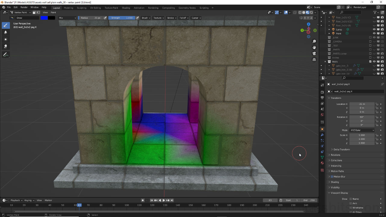
Whilst vertex colours are essentially baked to individual vertices they also propagate along edges. For example, blue and green painted to opposite corners of a face or area will blend correctly at the centre only if there’s a shared diagonal edge between the two points along which the colours can bleed. As a result the effect may bleed and blend across one face [16] or area but not another [17]. To address this issue Rotate Edge CW and Rotate Edge CCW can be used.

Although colour information is baked to individual vertices it does bleed along edges that can work for [16] or against [17] the effects distribution across the mesh depending on shared elements orientation.
To do this, toggle in to Edit Mode and select the face or group of faces to be amended. From the Face menu click Triangulate Faces [18] to break the selection into individual triangles – Face » Triangulate (alternatively Ctrl + T). Next, select the now exposed edge or edges that need to be rotated and from the Edge menu choose Rotate Edge CW or Rotate Edge CCW. The selection will rotate appropriately [20] depending on the number of times the menu option is clicked. Returning back to Vertex Paint (toggle out of Edit Mode) the colours painted to the mesh will be distributed based on the now modified edge flow [21].
Design note: “CW” means ‘Clockwise‘ (rotates top » right » bottom » left); “CCW” means ‘Counter Clockwise‘ (rotates top » left » bottom » right).

To correct the distribution or colour bleed faces need to be broken down into triangles to expose shared edges [18]…

… which can then be rotated [19] to change their orientation relative to corner vertices [20]…

… which in-turn change the orientation of vertex colour bleed [21] between individual painted vertices.
