Optimising Meshes for IMVU
Table of Contents
With the introduction of IMVU Studio mesh uploads are limited to around 10,000 or so triangles, anything above this limit now errors-out during import. In other words, products must now be more efficiently or effectively optimised for IMVU so they use as few polygons as possible. Whilst this applies to all high resolution (HD) products, Creators who purchase meshes may be particularly affected as they do not have source file access so will need to familiarise themselves with editing and optimising purchases for IMVU going forward.
Important: notwithstanding copyright issues, modifying third-party meshes may require additional licensing or rights that specifically accommodate editing or use beyond the authors original intent.
Optimising Principle
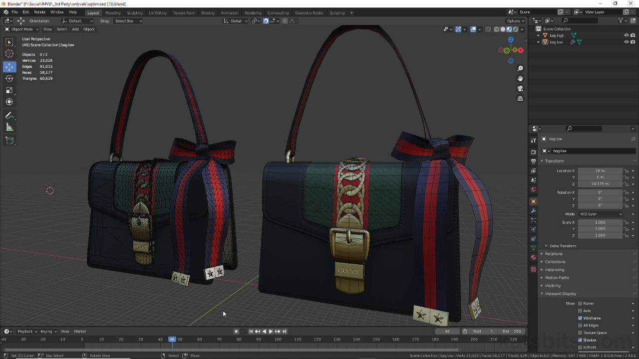
The basic principle of optimising is to reduce the complexity of an object to a minimum, maintaining its overall shape while conforming to any engine (technical) limitations on mesh density and/or texture usage. To do this the items silhouette can be used, the outline or outer profile presented to the viewer, as this more readily instructs on what something is supposed to be than any internal detail. Shown below for example very little difference is noticeable between the silhouettes of the same handbag accessory sitting side-by-side, one high resolution, the other low. In other words, all the structure that’s in place to make the high resolution version what it is does nothing to describe the object as would be used in IMVU, thus it can be removed.
Design note: as a general rule-of-thumb although silhouettes are a primary tool in determining the degree to which a mesh can be reduced, how aggressively this is done ultimately depends on the technical requirements of the environment into which the object is placed. In other words, individual items generally should not be more complex than the avatars that wear them and/or how closely they can be viewed or inspected in game (subject to what, and how big, the item is).

Green on the left is the high resolution (c. 55,000 triangles), white on the right is low resolution (c. 5,000 trianlges). Looking at the two side-by-side there’s little obvious difference between them, meaning, all that extra mesh structure in the high res is essentially wasted.

Shown in Material Preview with Wireframe overlay enabled, the difference between the two meshes becomes apparent, so too just how much optimisation can be done to the high resolution mesh (right-side).
Mesh Optimising
Generally speaking there are two approaches to optimising objects; manually editing meshes or procedurally reducing them using the Decimate modifier. Whilst the latter (modifier) is much quicker it’s also a lot messier, often producing structures that are chaotic and random, whereas the former takes much longer but typically results in much more organised structures.
Design note: generally speaking Decimate works best on organic forms where its random nature can be obfuscated or disguised by the objects shape.
To manually optimise, the mesh can be edited in Edit Mode using the standard tools alongside the various Dissolve options [1] to selectively remove structure; Dissolve Vertices, Dissolve Edges and Dissolve Faces – Mesh » Delete » Dissolve [option] (or press X » Dissolve [option]). Here vertices, edges and faces can be removed [2] while maintaining the overall integrity of the mesh [3], including the UV map.

Using Dissolve [1] the mesh can be reduced by selectively removing elements [2] while maintaining the overall integrity of the mesh [3] including any UV maps.
Decimate on the other hand only requires the modifier be applied to the mesh. Once placed (Modifier Properties » Decimate) the Ratio [4] can be changed (lowered) until a reasonable Face Count [5] is achieved, or the mesh looks respectable relative to being optimised for purpose.
Design note: the degree to which Ratio needs to be lowered depends on the initial face count of the mesh; extremely high resolution meshes may mean manually typing a fractional value, 0.1 or lower, due to the way such small increments are represented by the slider.

Once a Decimate modifier is assigned the Ratio value [4] can be lowered to reduce the Face Count [5] to a reasonable level or the mesh structure is sufficiently reduced.
Video overview using the Decimate modifier to (aggressively) reduce mesh density.
Optimisation Tools
Depending on the mesh the optimisation process might be easier with objects broken down into more manageable sections. This segmentation might be based on the items construction, by Material assignment, on UV mapping, by mesh selection or any combination therein. To this end, once an area is selected it can be detached as an independently editable object using Mesh » Separate » Selection [6] (or press P).
Design note: to aid the selection process use Select » Select More/Less » More or » Less (or press Ctrl + Numpad+ or Ctrl + Numpad –)

Use Separate [6] to break a larger more detailed mesh into smaller more manageable sections. Make a selection then use Mesh » Selection » Separate.
Once elements are separated they may then need to be converted from triangles into quads (faces) to better element selection and processing. To this end select two triangles [7] that would otherwise form a quadratic face [8] and from the Face menu click Tris to Quads [9] – Face » Tris to Quads (or press Alt + J).
Design note: conversion is selection based, it can be used on limited selections or everything.

Third-party purchased meshes tend to be triangulated [7] which make the optimisation process for IMVU difficult. To correct for this triangles can be selectively converted to quads (faces) [8] using Tris to Quads [9], which then makes broader selections easier.
To make the optimisation process easier surfaces and edges should be selected in loops or as part of a larger contiguous collection. In converting triangles into faces they sometime end up off axis in that they cause a discontinuation in edge or loop flow around a mesh. To fix this errant surfaces need to be broken back down into triangles – Face » Triangulate Faces (or Ctrl + T) – so shared edges can to re-orientated before being converted back into a quads. To do this, select a bad edge [10] and from the Edge menu click Rotate Edge CW (Clockwise) or Rotate Edge CCW (Counter Clockwise) – Edge » Rotate Edge CW/CCW – rotating the edge appropriately [12] to form a quad that’s conducive to fuller edge flow, loop selection and subsequent removal as needed.
Design note: although somewhat optional the purpose of fixing these types of orientation issues to better facilitate edge or face loop selections, that is, being able to select a contiguous strip of edges or faces from one side of a mesh to the other without having to make additional selections. It also reduces the amount of clean-up necessary where stray vertices, edges or faces remain in place after removal of something else.

Converting triangles sometimes causes breaks in edge flow (yellow) due to bad edge orientation [10] (red). This can be fixed using Rotate Edge [11] which changes edge direction [12] (green) so quads can be reformed that follow the natural flow of the mesh.
Video overview fixing loop selection/continuity issues.
Where edges or faces cannot be easily removed, for example their removal might break UV mapping, they can be collapsed using Edge Slide and cleaned up with Merge by Distance to remove any coincidental elements. For this, make a selection and click-hold the Edge Slide [13] icon in the Toolbar until the pop-out appears. Click Edge Slide. Click drag the yellow tool handle [14] to slide along the dominant edge to collapse elements together (alternatively make a selection and double-tap G). Next, select all then from the Mesh menu click Clean Up » Merge by Distance [15] – Mesh » Clean Up » Merge by Distance.

Where elements might not be removed using Dissolve it may be possible to slide [13] and then collapse them together [14], maintaining UV integrity in the process.

Once edges have been collapsed together the coincidental elements can be removed using Merge by Distance [15] which remove what are then unnecessary duplicate elements.
Video overview removing edges by collapsing and then merging using Merge by Distance.
Optimisation & UVs
Optimising a mesh using dissolve and collapse typically alters UVs by creating new and/or breaking existing bonds and associations. Whilst resulting texture distortions can be accommodated or worked around during the mesh editing process to varying degrees, it may be necessary to update and manually edit UVs directly to fix or address issues that occur.
Design note: optimising third-party meshes means working within set limitations, so whilst UVs might break and/or new bonds be formed, their doing so is relative to an existing layout and mapping. In practice this means the degree to which UVs can be fixed might be limited, for example UVs being merged or edited to fill gaps or disconnections but not moved wholesale to different areas of the map.

The reductive nature of optimisation will typically corrupt UVs [16] as new [17] and old [18] bonds are formed or broken as a result of the process.
Video overview fixing UV issues due to the reductive optimisation process.
Video
Time-lapse showing the process of optimising a high-resolution, third-party shoulder bag model for IMVU.
Design note: the original model starts out at around 55,000 triangles, which was reduced to c. 5,100. This is still relatively high for IMVU in terms of ‘an object’, but as discussed above when using third-party content, the degree to which something can be optimised is determined by the items original construction and assets use.
A one hour time-lapse reducing a 12+ hour process of optimising a mesh for IMVU (no audio/no narration).
