UV Editing (Workspace) Basics
Table of Contents
For the most part UV Editing in Blender remains largely unchanged from previous versions in that UVs, once unwrapped, can be edited in the dedicated UV/Image Editor, or in the task specific UV Editing Workspace (layout). The same manipulation tools are also available, now accessible using a set of tool specific icons, each additionally having a specific mode of operation that generally won’t interfere with others when active. The following is an basic overview of the UV Editing Workspace.
Important: with the removal of Blenders obsolete internal rendering engine (Blender Render or Blender Internal) objects now require material assignments else they will appear untextured when Material Preview or Rendered display modes [1] are active. In other words images mapped directly [3] to unwrapped objects [2] are not immediately shown.
Images assigned direct to UV maps are not displayed in the 3D view without a corresponding fully qualified material also being assigned so, although objects may be properly UV unwrapped [2] and mapped [3], they will appear untextured (white) in the 3D View [1] (Material Preview or Rendered display modes).

UV Basics
As briefly mentioned above, the changes to Blender rendering capabilities now mean texturing (using UVs) is a three-step process;
- Unwrapped the object.
- Create a material with image.
- Map image to object.
Where previously it was possible to omit step ‘2’ and assign an image directly to an objects UVs, doing so now generally means those objects appearing untextured in the main 3D View and Shader Preview, or render incomplete in Render output (either Eevee or Cycles), and/or content exporting incorrectly for external use. To avoid these problems everything has to be properly set up per the above with materials assigned [6] so textures appear in the various 3D views [7].
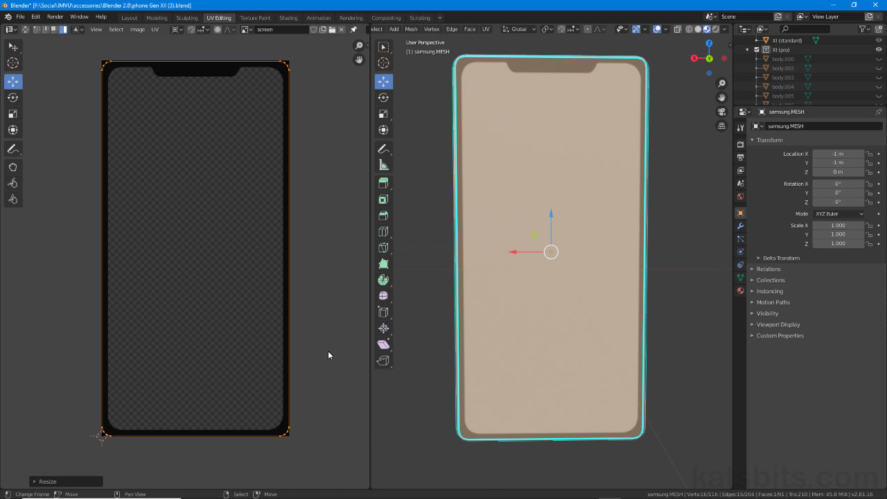
Design note: the order in which the above is carried out is not as important as their all being included and/or assigned. Once done images will appear based on whatever UV map is found – if a UV map is not available (check Object Data Properties [4] under UV Maps [5]), once materials are assigned meshes may appear colour tinted rather than white as would otherwise be typical (the colour is essentially as distillation of the colour-values contained within the image that’s associated with the Material and generally cannot be edited directly – it does not function like Diffuse or Base Color properties).
If UV maps are not available [5] but materials have been assigned, meshes may appear colour-tinted if the materials ‘diffuse’ colour (Base Color) is set, or alternatively extrapolated from an image if linked (but not yet mapped) – the barrel above is tinted a light tan colour for this reason.

In practice UV maps can be generated a number of ways; they might be auto-generated as part of Add » Mesh » [option] process that drops a mesh primitive into the scene, or manually created in Edit Mode using the available UV menu (U) options. Either way, once a map has been created, generated or is available it can then be further edited in the UV Editing Workspace.
Design note: use Mark Seams (Edge » Mark Seams) to break UVs into manageable sections or relieve ‘stresses’ in maps to prevent overt stretching or distortion – to do this, in Edit Mode select the edges where a Seam should be placed (e.g. Shift + click for multiple edges) then from the Edge menu select Mark Seams (Edge » Mark Seams). The edges will immediately highlight orange confirming assignment.
A simple low-poly barrel with Seams marked around the mesh, highlighted orange, that help to relieve the UV map so it can lay flat and not distort, especially important for round or organic shapes and forms.


For objects to appear textured in the 3D viewports [6] they need to have fully qualified material assignments, i.e. materials, even basic ones, that include an Image Texture node to which an Image is assigned [7] (and external bitmap or internal generated data).
UV Editing (Workspace)
Blender now being Workspace orientated means that editing UV maps is going to be carried out largely in the UV Editing Workspace. Here Blenders layout changes to show the UV Editor occupying the left side of the application where most, if not all, UV editing and manipulation occurs, the 3D View on the right (the Properties and Outliner editors remain unchanged) where faces and elements are selected to highlight associated UVs.
Design note: when switching to the UV Editing Workspace Blender automatically switches the 3D View’s context to Edit Mode focused on the last active obejct so selection prior to activating may not be absolutely necessary – editors and layouts typically have their own display defaults and/or will remember the last used state.
When switching to UV Editing Workspace the last selected item will be shown in Edit Mode if no object is active in the 3D View – the Workspace has its own defaults that will display a selection and associated UVs (where available) in the UV Editor.

Like other editing areas, the 3D View to the right for example, the UV Editor also includes a set of tools and options; a Toolbar [8], shortcut T, running down the left-side; a menu Header [9] running along the top; the Sidebar [10], shortcut N, on the right (typically hidden by default).
Important: as of Blender 2.80 the UV/Image Editor is now two independent areas, the UV Editor and Image Editor (Shift + F10), the latter being where images can be edited and manipulated directly, e.g. when image painting. This now means when objects are in selected in the 3D View the Image Editor no longer displays UV information (Edit Mode), this is now exclusively handled by the UV Editor as part of the UV Editing Workspace.
Shown above the Image Editor is selected (using the Editor Type selector), which no longer displays UV information. This is instead now done in the UV Editor, an area dedicated to the task of editing UVs and UV maps.


The UV Editing Workspace reorganises Blender, splitting the screen more-or-less in half, the left side is the UV Editor where UVs will appear; the right is the 3D View that facilitates face/UV selection (Properties and Outliner editors remain in place).
The UV Editing Workspace now has a set of manipulation tools that bring it inline with other content editors; a Toolbar [8], a comprehensive Header [9] and a Sidebar [10] (typically hidden by default).
Toolbar – Select
Introduced with Blender the UV Editor itself now includes a complimentary set of manipulation tools and widgets that bring it inline with other editors, first being the Select tools for making UV component selections, be they vertex, edge or face (cf. below); Select Box (Shift + Spacebar, B) – draws a linear box or right-angled outline, Select Circle (Shift + Spacebar, C) – draws a fixed-sized circle around the mouse cursor, and Select Lasso (Shift + Spacebar, L) – draws a user delineated selection outline. To use, select an option from the list, or use the appropriate shortcut to active and left-click drag an area, or paint to mark a selection.
Design note: the traditional shortcuts, B for Box Select and C for Circle Select still function as always (including the use of middle-mouse scroll to decrease/increase selection area) but provide a slightly different user experience to the dedicated modes described. Ctrl + left-click drag still activates Lasso Select.
Using the old shortcuts from pre-Blender 2.8 provides for a slightly different user experience (although performing the same functions) compared to the dedicated selection tools in the Toolbar.


In the UV Editor, with the Select Lasso icon active in the Toolbar, simple click-drag around the workspace to describe a selection outline – anything inside, vertex, edge or face (or Island) will be included in the selection made.
Toolbar – Cursor
A new introduction with Blender 2.8 is Cursor mode. Activated clicking the Cursor icon [11] in the Toolbar, this allows the 2D Cursor to then be dragged and incrementally positioned[13] without interfering with other operations (except middle-mouse manipulations of the viewport). To use, just click or click-drag to place or position when Cursor mode is active.
Design note: the 2D Cursor can still be placed anywhere during any operation, the new Cursor mode just adds more control over how the widget is positioned on screen, it can be dragged around as well as click-placed.
For more accuracy positioning or placing the 2D Cursor [15] access the SideBar – View » Sidebar or press N – and in the View options edit the X and Y values for Cursor Location settings in the 2D Cursor section [14].
Design note: coordinates are proportional and relative to the Texture Space, the bounding-box or area defined by the image open in the editor, X/Y 0.000 is bottom-left, X/Y 0.500 is centre-mass, X/Y 1.000 is top-right.

When Cursor mode [11] is active the 2D Cursor widget can be dragged around the workspace [13] which also displays a set of coordinates in the upper left-corner of the view [12].

The 2D Cursor can be positioned more accurately [15] from the Sidebar (N) by changing the X and Y values under Cursor Position [14].
Move, Rotate, Scale
The addition of the Toolbar to the UV Editor also means a set of dedicated manipulation modes are available that mirror other views, in particular the 3D View. Here icons are provided to engage Move, Rotate and Scale, which behave the same as when activated using their respective shortcuts, M (Move), R (Rotate) and S (Scale), with an additional Transform mode [16] combining the three into one tool.
Design note: as is common to other editors, when a transform mode is activated using a shortcut key (G/R/S) the corresponding Toolbar icon remains inactive. Shortcut keys can also be used to activate other manipulation modes independently of whichever Toolbar icon set.
When a manipulation mode is set in the Toolbar, Move for example, pressing the R key to Rotate a selection overrides this, resetting back to Move once the action is completed.

For UV editing this latter tool, Transform [16], when activate displays a 2D manipulation widget that allows UVs to be manipulated in various ways depending on the control element click-dragged [17]; an edge to make lateral changes (scalar) along the X or Y axes; a corner to make bilateral changes on both X and Y (diagonal scaling); a node for rotational changes; and a centralised ‘X’ for pan or X/Y translations.
Design note: the 2D widgets changes slightly depending on the selection type set; with Vertex Select active an red and green X/Y arrow widget appears allows for lateral manipulation of individually selected vertices only – multiple vertex selections cause the normal manipulator to appear as described above.
When the Transform widget is active and Vertex Select set it changes to an red and green X/Y arrow set (allows lateral manipulation of individual vertices only).


When Transform is active [16] a 2D manipulation widget appears in the editor [17] that allows for UV to be changed depending on the control element selected; edges to scale X or Y, corners to scale both X and Y, center to move X and Y and a node to rotate.
UV Selection Mode
Selecting UVs remains unchanged, icons being provided in the area Header for Vertex, Edge, Face and Island. To use, click the appropriate option to activate, or alternatively use the shortcuts 1 (Vertex), 2 (Edge), 3 (Face) or 4 (Island), then click the UV’s element type in the workspace – vertex, edge, face or island component to highlight, Shift + click to multi-select.
Design note: as for selection modes generally multiple modes can be activated at the same time, simple Shift + click to activate other options.

Setting the UV selection mode clicking the UV Selection Mode icons; Vertex, Edge, Face or Island. Each selects a different component type similar to mesh selecting in the 3D View, so vertex, edge and face primarily with island being unique to UV editing, facilitating the selection of a larger separated collection of UVs.
Snap UVs
For Blender UV snapping is catered to by Snap, Snapping (Snap during transform) and Snap to Pixels, and similar to other editors and areas, each solves a particular problem or serves a specific function.
Important: UVs are typically snapped (grid and pixel especially) as an optimisation technique meant to reduce the degree to which vertex coordinate data ‘floats’, that they resolve to whole numbers instead of decimal fractions, e.g. 2.000 instead of 1.983.
Snap is largely used to collapse selections to the 2D Cursor or to snap UV vertices to the nearest pixel, useful for tidying up general UV vertex alignments. To use, first make a selection in the UV Editor then from the UV menu select Snap » [option], e.g. UV » Snap » Selected to Pixels. Alternatively press Shift + S to access the Snap pie menu.
Design note: generally speaking Snap functions similarly to Edit Mode’s object, element or selection snapping.

In the UV Editor when active, Snap acts like Edit Mode’s ‘snap to…’ so a selection can be snapped to a target, a vertex, the 2D Cursor or other option.
Snap or Snapping (Snap during transform) is generally useful for snapping selections to fixed increments as they are being manipulated or snapping to other UV vertices generally using the selections centre as the pivot (focal) point. To use, first activate Snap clicking the magnet icon in Header of the UV Editor, or using Shift + Tab, then click the Snapping icon to its right and set/selection an appropriate option; Increment or Vertex. Manipulating selections will then snap based on the active option.
Design note: although Snapping functions similarly as it does in the 3D View it differs in that the UV Editor grid uses fixed increments regardless of image size, when set a proportionally relative 16 x 16 grid is measured in increments of 1/16ths or 0.1250 per division/unit. Units of Measurement do not affect this feature.

Snapping (Snap) acts like grid-snapping but is limited to proportionally relative increments of 16ths (1/16th per increment or 0.1250 per division from 0.000 to 1.000).
Snap to Pixels is typically used to realign UV vertices so they snap to individual pixels, image pixel density essentially defines the grids division density – pixel density corresponds to grid-snap density. To use, from the UV menu in the Header select Snap to Pixels » [option] e.g. UV » Snap to Pixels » Corner. When UV vertices or selections are moved they will automatically snap to the nearest pixel target.
Design note: image size (dimensions) determine Snap to Pixels precision, larger images occupy more Texture Space than smaller ones allowing for greater precision. In other words image size defines snap granularity, a 10242 image creates a grid with 1024 divisions, a 642 image one with 64 and so on.
![]()
Specific to the UV Editor (and Image Editor) Snap to Pixels uses a grid that’s defined by texture size and corresponding pixel density in the editor, the larger the image the better the precision due to increased granularity of the grid.
Pin UV
To aid UV editing and unwrapping Pin can be used to fix vertices in place [18], preventing incidental or indirect change whilst modifying other elements [19] of a map. To Pin, first make a selection in the UV editor then from the UV menu select Pin – UV » Pin. Pinned vertices will immediately highlight red. Alternatively make a selection then press P.
Design note: although UV selection can be made in Vertex, Edge, Face or Island selection mode, pinning only applies to UV vertices. Once pinned vertices can then only be moved or modified directly (direct selection and/or manipulation), for example if a UV map is regenerated, pinned vertices remain fixed resulting in a warped map that accommodates the pinned elements.

UV vertices can be Pinned [18] to prevent accidental changes when editing other UV elements [19], simply make a selection then from the UV menu select Pin, or press P.
