UV Map Basics
Table of Contents
For newer versions of Blender UV Maps play a more important role because, with the removal of the now obsolete Blender Render engine, textures and materials are not rendered on surfaces without them. For correct display this means objects need to be UV Unwrapped, and images UV Mapped to those unwrapped surfaces, before anything is seen, requiring a basic understanding of UV Maps.
Important: see UV Editing (Workspace) Basics for more on UV editing generally.
UV Map Basics
UV Maps are essentially two-dimensional representations of three-dimensional structures that have been processed, or unwrapped, to form an otherwise flat layout or map of an object to which an image or material can be assigned. In other words, for a mesh to appear as though its made from wood, a 2D map of the object is needed for the wood texture to appear correctly positioned on the mesh when viewed or rendered. This map is the objects UV Map, the process of creating it, UV Unwrapping.
Design note: although UV Unwrapping and UV Mapping are technically distinct terms they are often used interchangeably to refer to the same process; mapping or preparing an object for image assignment.

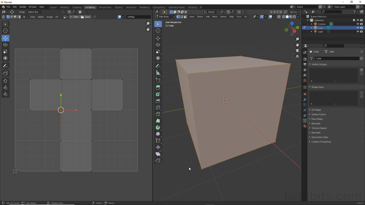
UV Editing Workspace showing a simple (default) Cube mesh object UV Unwrapped (right) to create a UV Map (left) ready for an image to be mapped so it appears in the 3D Viewport.
UV Map Elements
UV maps are edited, manipulated and managed in the UV Editor, or UV Editing Workspace, using the same basic compositional and selectable elements as a mesh in the 3D Viewport, i.e. a Vertex [1], Edge[3], Face [5], and UV editing specific, Island [7]. Each has a corresponding UV Selection Mode so the different elements can be selected and manipulated individually, or as part of a larger group or collection, using the Move (G), Rotate (R) and Scale (S) tools available in the UV Editor Toolbar (T) down the left side of the editor. With these, UVs, individually or as part of a larger collection, can be manipulated relative to the square workspace grid that represents the area occupied by an image, the Texture Space, it’s this area that determines the ‘what’ and ‘where’ placement of UVs with respect to any image mapped to an object. To set the UV Selection Mode, in the UV Editor click the appropriate button in the UV Editors Header, Vertex, Edge, Face, Island, or press (main keyboard) 1, 2, 3 or 4 respectively.
Design note: when working with UVs and the UV Editor generally, although there are a number of different element types available – Vertex, Edge, Face, Island – they are generally all displayed, but not necessarily selectable, at the same time regardless of the active selection mode. For example the vertices of Vertex selection mode are displayed in place at UV corners and junctions even though Island segments might be the active selection and mode set.


Each element that constitutes an UV map has its own selection mode;
Default UV Maps
Most of Blenders mesh primitives, that is the Cube (scene default), Plain, UV Sphere, Ico Sphere, Cylinder, Cone and Torus, the objects generally dropped in to and edited in the 3D Viewport, are essentially pre-unwrapped to include a basic UV map that’s ready for use (image assignment). In other words in dropping one of these primitives into the scene, Add » Mesh » [primitive] (or Shift + A), the included UV map then only needs to be updated or modified, not created or generated.
Design note: the default UV maps are generated such that they fit within the boundary of the available Texture Space (the grid area in the editors workspace). As a result UV maps may not be specifically optimised for the shape represented relative to the amount of space available.

Each of the default mesh primitives (except Circle object) is UV Unwrapped and carries a basic UV Mapped that can be left as is, or edited in the UV Editor (UV Editing Workspace) – the maps primarily serve so objects have an appropriate UVMap data block in the UV Maps subsection of Object Data Properties (see below).
Generate UV Map – UVMap
Internally UV Maps are not just a flat representation of an object, they’re an editable component of an underlying datablock, UVMap. In practice this technically means editable UV maps can be generated in two ways; 1) adding a UVMap datablock, or 2) unwrapping the object using Unwrap options. In either instance a UVMap datablock is generated and displayed in UV Maps (Object Data Properties), accompanied by an editable UV map shown in the UV Editor.
Design note: the difference between adding a datablock or unwrapping an object essentially boils down to; unwrapping objects allow for UVs to be edited for visual affect, whereas creating datablocks allows for multiple UV maps to be assigned to a single object, each map has its own datablock, which can then be selected in UV Maps list in Object Data Properties for editing in the UV Editor (each datablock is typically assigned a reset UV map – see above). Below for example, the UVMaps aperture list in Object Data Properties, displays three different datablocks, each accompanied by a unique UV layout that can be modified wholly independently of the other available datablocks.
Using UVMap datablocks objects can be assigned multiple UV maps [a-c], each being different from their neighbours, mapped to specifically associated images; top – reset [a], middle – default [b], bottom – individual faces [c].


To generate or create a new UVMap datablock, in Object Data Properties click the + button [9] to the right of the UV Maps aperture. An entry appears named UVMap [10]. Looking to the UV Editor on doing this a UV map will have been created, faces mapped individually 1:1 to the available Texture Space, essentially resetting the objects UVs in its entirety. To create additional UVMap datablocks click the + button again, double-click each entry to rename as required (Blender defaults to using an incremental numerical append to make each instance unique, i.e. *.001, *.002 etc. or UVMap.001, UVMap.002) etc., press Enter to confirm.
Design note: when creating a UVMap datablock the associated UV map is typically reset and mapped 1:1 to the available Texture Space represented by the editor grid regardless of face, triangle or ngon selection. In other words, a square UV will fill the square grid, a triangle half on the diagonal, and an ngon based on the number of sides.
A UV Sphere object (right) with UVMap datablock assigned has its UVs essentially ‘reset’ so each face occupies the entire available Texture Space (left). This is typical for all mesh objects when adding UVMap datablocks to an object – red = ngon, blue = face, green = triangle.


Creating a new UVMap datablock in Object Data Properties, click the + button [9] then rename the map if necessary [10] (especially if several maps are being used – some game development environments require multiple maps to follow a specific naming convention).
Generate UV Map – Unwrap
To create a UV map manually using Unwrap, with an object selected in the 3D Viewport and in Edit Mode – UV Editing Workspace does this automatically when active – ensure the faces or area to be UV unwrapped are selected, then from the UV menu [11] in the UV Editor, select Unwrap [12], then Unwrap [13] – UV » Unwrap » [Unwrap/option]. Alternative in the 3D Viewport click the UV menu [14] then Unwrap [15] or another option – UV » [Unwrap/option]. In either instance the mesh will be unwrapped and UV map generated based on the option chosen and/or whether the mesh has been ‘marked’ to accommodate UV mapping with Seams, Edge Split or other modification (see below).
Important: by default UV editing is selection based, that is, UVs must be selected in the 3D Viewport before being displayed in the UV Editor. This behaviour can be disabled (toggled) by enabling UV Sync Selection [d], which displays the entire UV map regardless of mesh selection in the 3D Viewport. UV Sync Selection also highlights selection correspondence [e], that is, editing a UV vertex or edge in one location [ii] highlights and synchronises manipulations between all positions that vertex or edge might appear in the overall UV map [i & iii]. Faces however, differ. When UV Sync Selection is active, and the selection mode set to Face, selections behave as though they are Split [f], and can be manipulated independently of neighbouring surfaces without affecting other areas of the overall UV map.
Image top: Enabling UV Sync Selection [d] disables the default selection-based display of UVs in the UV Editor, which also then show connected elements for each selection [e] – these move in sync when edited. Image bottom: when UV Sync Selection is active, face selection and manipulation is as if they are Split or detached all the time [f], corresponding faces are not highlighted and can be moved independently of surrounding faces.


Design note: if the mesh has not been prepared for unwrapping the resulting map is typically ‘reset’ so each face is mapped one-to-one with the Texture Space.

To generate a UV map using Unwrap, from the UV Editor click the UV menu [11], Unwrap [12] and then an option, typically Unwrap [13]. The creates a UV based on the options selected and whether the mesh (select faces) have been treated for unwrapping (Seams etc.).

UV maps can also be generated in the 3D Viewport and the UV menu [14] that’s available when in Edit Mode – make a selection and access the UV menu then select Unwrap [15] or other option as needed.
Edit UV Maps
Subject to a mesh being UV Unwrapped and a UV Map available, to display and then edit UVs, by default surfaces need to be selected in the 3D Viewport, on their own (single), as part of a group (multiple), or the mesh in its entirety (all). When this is done UVs corresponding to the selected surfaces highlight in the UV Editor, which can then be edited or manipulated [16] using the tools available in the Toolbar to the left [17], based on the UV Selection Mode set [18], e.g. UV vertices being realigned using the Move tool because Vertex selection mode it set.
Design note: see UV Editing (Workspace) Basics for more on the UV Editor and editing UV maps.
Important: subject to UV Sync Select (see yellow boxout), by default UVs do not display in the UV Editor [i] unless complete faces are selected in the 3D Viewport, in other words, selection needs to be of intact triangles, faces or ngons using any selection mode, Vertex, Edge or Face [ii].
UVs don’t display in the UV Editor [i] unless intact surfaces are selected in the 3D Viewport regardless of the selection mode, Vertex, Edge or Face, used to select triangles, quadratics or ngons.


To see UVs in the UV Editor corresponding faces need to be selected in the 3D Viewport. Once this is done UV elements [16] can be manipulated using the available tools [17] based on the selection mode set [18].
In addition to editing UVs based on Vertex, Edge, Face and Island selections, they can be broken apart using Split so vertices, edges, and faces can be manipulated independently of their surroundings or connecting elements. To do this, in the UV Editor set the Selection Mode and make a selection. From the UV menu click Split then Selection – UV » Split » Selection [21] (or press Y). Depending on the selection mode this will break the selected elements apart, or detach them [19], from neighbouring elements [20] allowing further editing of the UV independently of their surrounds.
Design note: generally speaking Seams should determine how UVs are segmented or broken apart for mapping – splitting UVs as described here can lead to unnecessary surface splits in the mesh which might then break Smoothing, so care should be exercised creating content for use outside Blender.


UVs generally cannot be edited independently of their neighbours. However, this can be done in the UV Editor after a selection is made using Split. Image top: the basic elements broken into their constituent parts; one vertex splits into several depending on the connecting vertices, edges split similarly depending on connecting edges, and faces split based on intact selections. Image bottom: a single UV face [19] (image bottom) is moved away from the larger selection [20] after its been separated from the group [21].
Similarly UV elements can be joined in the UV Editor using Merge, this allows for different UV configurations within the UV Editor to suit the image being mapped to an object rather than an object being mapped to an image. To do this, make a selection then from the UV menu select Merge, By Distance or other option – UV » Merge » By Distance [22] (or press M). This collapses elements [23] and/or joins them together [24].
Important: by default Blender automatically merges UV vertices that are in close proximity or coincidental to one another when selected, or where not, will behave similar to the By Distance option available in the Merge menu. In addition, UVs can only be merged where a physical relationships exists between elements – it is not possible to merge a given UV from one side of a map with that on another unless there is a ‘shared’ vertex, edge or face between the two.

When using By Distance [22] a threshold can be used – Merge UVs by Distance [23] – to Merge UV vertices together [24], essentially the same ‘remove doubles’ function available to meshes in Edit Mode but for UVs (and UV Editor).
Optimising UV Maps
The overall structure and general appearance of a UV map is determined by the mesh being unwrapped and the way that might be marked with Seams to force splits, separations, or other detachments, between elements that do not necessarily need to reflect the object being unwrapped, or represent the best layout therein. In other words, maps do not specifically need to retain their original form so can be modified, parts shuffled into space that would otherwise remain unused. This is, in essence, what UV Optimisation is, the (re)organisation of an objects UVs to take full advantage of any available Texture Space.
Design note: generally speaking UV layouts sit within the space defined by the gridded area of the UV Editor (Texture Space), but may extend beyond (Texture Bounds) depending on requirements, i.e. unwrapping a UV that tiles across a large object.


Image top: the default UV map uses six (6) of the available sixteen (16) units, ten (10) remain. In terms of raw numbers this indicates an inefficient layout. Image middle and bottom: show the same map split into faces and reorganised to make better use of the space, the remained then clear to be used for other items (multi-object mapping) or parts of the same object.
With this in mind, when organising UVs two general considerations should be kept in mind; 1) UVs relative size or scale, and 2) keeping texture density consistent across all UVs. In practice this might mean small UV sections being scaled up to prevent pixilation, larger islands being scaled relative to each other so texture patterns match across surfaces, or individual UVs being placed atop each other for 1:1 mapping.
Design note: a great deal of UV map optimisation is determined by outcome. In other words the UV map for a particular object might utilise a combination of approaches, small mesh details might use slightly larger areas of an image to increase texture density while other relatively unimportant sections use overlaid UVs. In practice optimisation does not always obligate or require exclusive use of one approach to UV optimisation over others, the point of is achieve the best outcome possible within the bounds of the mapped image.
In practice most UV maps tend to use a combination of approaches to mapping depending on the mesh and how some sections might need to appear more visually detailed than others, for example different areas might need unique texturing [i] whereas as others repeat, in whole or part, so UVs repeat using different areas [i] of the mapped image [k].


Image top: the default UV map and corresponding texture density (UVs are rearranged so each UV face occupies a single ‘unit’ of the assigned image for clarity). Image bottom: rescaled UVs increases texture ‘density’, how much image is dedicated to a given face, which can improve image clarity.
