Bake Lightmaps (Light Maps)
Table of Contents
Using Texture Bake to generate Light maps in Blender is roughly the same as it is for other types of image baking. However, because lightmaps generally serve a particular purpose, only typically including shadows or shading, they are often assigned to their own material or image data and rendered to their own UV, an additional ‘layer’ belonging to the object or objects being rendered. To be effective then, some prep and set up is needed before baking.
Important: Blender is by no means a ‘lightmapper’. Whilst it can bake shadows and shading sufficiently to be considered a ‘lightmap’, mileage from doing so may vary significantly depending on the intended use of the resultant texture bakes. See also Exporting Lightmaps
Object & Scene Setup
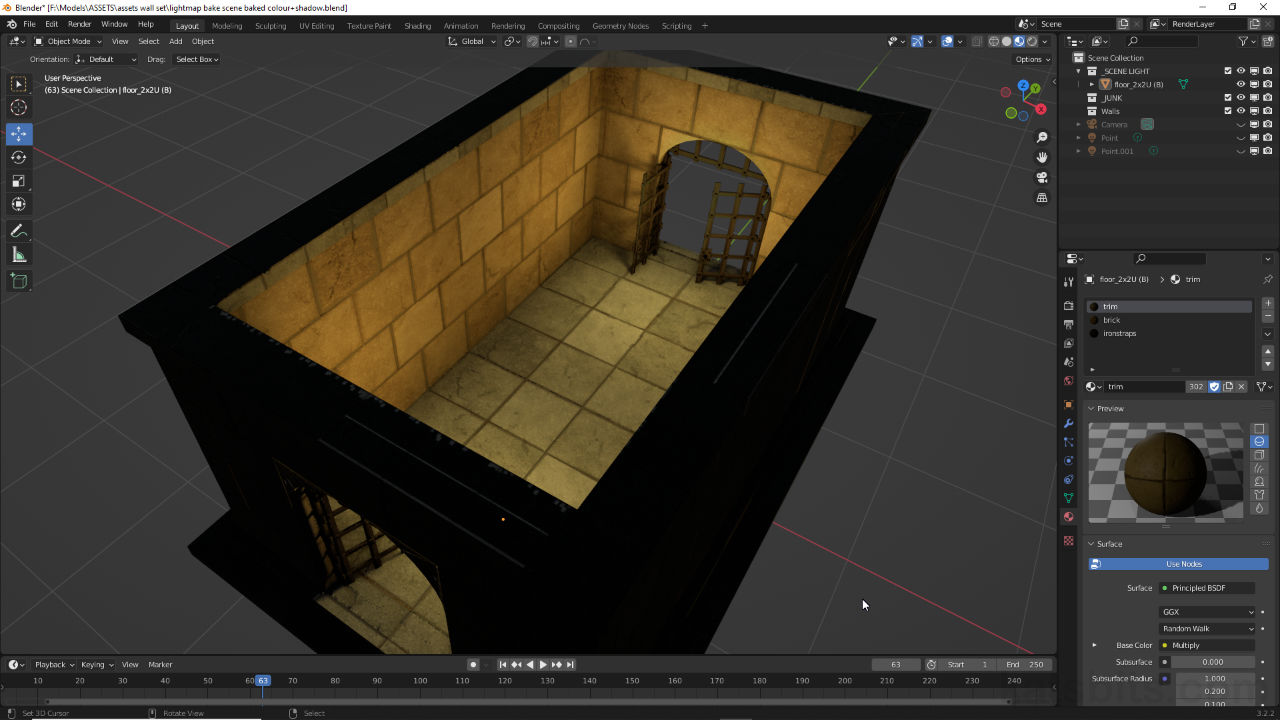
Before baking a lightmap with Blender make sure the objects to be processed are appropriately lit. Dynamic lights [1], that is Spot, Sun, Area and Point, and static illumination, emissive materials, Ambient Occlusion (Render Properties » Ambient Occlusion) or background colour [2] (World Properties » Color), should be set relative to visual expectations as previewed using Rendered display mode for Eevee or Cycles [3].
Important: when lighting an object or scene in Blender a great deal depends on how the final assets are to be used. Exported for import and assembly in third-party tools and editors, objects and scenes will typically need to replicate or at least approximate different types of lighting and their placement which may not always be possible. For example some forms of static lighting do not cast or emit light in Blender but do in other sources so temporarily light placement may be necessary in Blender to capture an object or scenes general illumination relative to those third-party uses.

To bake lightmaps the scene or objects to be baked need to be lit using light entities [1] or scene properties [2], previewed using Render display mode [3] for either Cycles or Eevee renderers.
Similarly objects should be correctly marked Sharp (Edge » Mark Sharp) [4] and Smoothed (Object » Shade Smooth), be fully UV unwrapped and mapped [5], as well as being textured appropriately because these aspects of asset prep, smoothing, images, materials and their properties potentially influence lightmap baking.

Objects themselves need to be prepped, Sharp edges and smoothing [4] as well as being fully UV unwrapped and mapped [5], with materials and images appropriately assigned as these all potentially influence the bake process.
Lightmap Material Setup
For Bake to work correctly a dedicated texture slot is needed that in-turn, hosts the image actually rendered to. This additional material node can be added to, or included within, existing materials. To do this, ensure the object to be baked has an existing material assignment [6] then in Shading Workspace drop an additional Image Texture [7] node into the Node Editor – Add » Texture » Image Texture and to this new node add an Image clicking the New + button. In the New Image [8] pop-up create an image, set the; Name, e.g. “lightmap”; Width and Height, e.g. Width 2048, Height 2048; and Generated Type e.g. Blank, UV Grid or Color Grid.
Design note: the image added here is temporary and only serves as the substrate to which lightmap data is rendered. Size may vary depending on where the image is to be used so some width and height limitations may apply. Similarly, larger images will take longer to render lightmaps to (also relative to UV complexity).

Materials to be baked [6] need an additional Image Texture [7] and Image [8] association as this is what the rendered bakes lightmap data to.
Next, as lightmaps should be set up to use a dedicated UV map channel, Blender needs to be able to distinguish between the standard images associated with the material as seen on the mesh, and the lightmap. To facilitate this two UV Map nodes need to be included and linked to other nodes appropriately. To do this click Add, then in Input select UV Map [9] – Add » Input » UV Map. A UV Map node will appear. Click to drop into the editor [10].

To ensure lightmaps remain separate elements of existing materials they need the own UV Map nodes. From the Add menu select the UV Map entry from the Input options [9]. Repeat so two nodes are available [10] for linking.
Repeat or select the new node and copy/paste a duplicate into the editor. There should be two UV Map nodes. Link the UV output from one of the UV Map nodes to the Vector input of each Image Texture associated with the standard Principle BSDF or other base material, then click the UV coordinates to be used for mapping input field and select the existing map from the list (typically UVMap) [11]. Link the second node to the lightmap Image Texture; UV output to Vector input [12]. Leave the UV map blank for now. Selecting the lightmap Image node [13] should then display the generated image created earlier [14].

Blender needs to distinguish between UV maps so UV Map nodes are added and linked to the Image Texture nodes of the base material [11] and the lightmap section [12].

One the material nodes are set up, selecting the lightmaps Image Texture node [13] will display the generated image [14] ready for the bake process.
Finally, where objects have several materials assigned, each needs to reference the same image and UV data. For example, if ‘trim’ was set up as described above, the additional nodes should be duplicated to ‘brick’ so it too has an extra Image Texture referencing the same generated ‘lightmap’ Image. Similarly for the UV Map nodes. To do this select each unmodified material in-turn and rebuild the additional nodes as described or copy/paste the lightmaps Image Texture node and the two UV Map nodes – shift + click select the nodes then use Ctrl + C to copy, Ctrl + V to paste into the node editor as each unadjusted material in selected. Link the nodes as described above, UV outputs to Vector inputs.
Design note: to wrangle several materials more easily, in Shading Workspace mouse over the Node Editor (bottom half) and press Ctrl + Spacebar to toggle the editor full screen (Ctrl + Space again returns to previous layout). Individual Materials can then be edited after selection from the Browse Material to be linked list [i], which displays all materials available in project, or from the Active Material Index list [ii], which shows materials assigned to active (selected) object in the 3D Viewport. Once a Material is selected the Node menu provides a number of options for basic node editing, including copy and paste – Ctrl + C and Ctrl + V [iii] – select the nodes to be copied, copy, switch materials and then paste.
Using the Node Editor to wrangle multiple materials but selecting them using the Browse Material to be linked [i] list or the Active Material Index [ii] where nodes can be copied between trees [iii].


If the objects to be baked are assigned more than one material they all need to be prepped in the same way to include a separate Image Texture node and two UV Map nodes, each linked to their respective material sub-tree. Shown above for example two materials, ‘trim’ and ‘brick’ assigned to the same object, include identical lightmap node set-up and linkage.
Lightmap UV Map
For Bake to work correctly when rendering lightmaps, objects included in the process need an additional UV Map channel to accommodate the way UVs have to be unwrapped for lightmapping, in essence each face is mapped as a separate UV element rather than part of a larger ‘island’ or group of UVs as would normally done. This can be done several ways; adding another UV Maps channel in Object Data Properties and then unwrapping the mesh while that’s active, or having the lightmap UV channel added during the UV Unwrapping process using the New UV Map checkbox.

Generally speaking the UVs needed for lightmaps are organised in ways that don’t make necessarily sense under normal circumstances. On the left is a typical (but simple) UV map and layout that represents how the object is textured and seen in use, whereas on the right is a ‘lightmap’ UV layout that breaks UVs into individual units so the can be laid out more effectively to use as much Texture Space as is available.
Single Object Lightmap UV
UV unwrapping a single object for lightmap baking is relatively straightforward, with object selected, in Object Data Properties [15] click the UV Maps heading to access the sub-sections options then click the + button [16] to the right of the Active UV Map Index aperture. A new entry, UVMap.001, appears, double-click this and type “lightmap” or similar identifier to rename for clarity. To the right of the new listing click the camera icon [17] to make this channel the active UV map.
Design note: this initial step can be done wherever the Object Data Properties and UV Maps data is accessible, typically Layout (default UI), UV Editing or other Workspace, editor or area.

Before lightmapping an object it needs a dedicated UV Map channel. In Object Data Properties [15] this can be done in UV Maps; click + to add [16] then rename and enable clicking the camera icon [17] making this new entry the active UV map.
Once the channel is available, ensure the entire mesh is selected in Edit Mode then from the UV menu in either Layout or UV Editing Workspace, click Unwrap, then Lightmap Pack [18] – UV » Unwrap » Lightmap Pack. In the Lightmap Pack [19] overlay popup that appears set Image Size, Pack Quality and Margin, based on the size of the image set, for example 1024, 1 and 0.16. Click OK to unwrap the mesh generating the lightmap UVs [20], then finally assign the previously created lightmap image using the Browse Image to be linked dropdown [21].
Design note: when setting Lightmap Pack properties; Image Size sets the overall dimensions of the map, 2048 for example defines both width and height and so on; Pack Quality changes the dimensions and distribution of individual UVs within the square bounds set by Image Size, set to “1” UVs typically retain their original dimensions, “48” and squarer UVs will be forced square dimensionally to fit; Margin increases or decreases the distance between individual UVs – higher values may be needed for clearance on smaller images to allow for pixel bleed and anti-aliasing.
Pack Quality changes the UVs so larger elements are more uniformly square and better able to fit within the bounds of the available texture that’s mapped to the UV layout – image-left, UVs reflect their original shape more or less, image-right, UVs are reshaped for a better fit.


Once the UV Map is available and selected as the active object in Object Data Properties the mesh can be unwrapped from the UV menu using Lightmap Pack [18] where Image Size, Pack Quality and Margin [19] can be set based on how large the lightmap UV layout should be…

… click OK in to finish Lightmap Pack and generate the UVs relative to the settings used [20], then assign the image previously created using Browse Image to be linked [21] (the image won’t appear on the mesh in the 3D Viewport as it’s not linked to the materials Base Color input).
Single Object Lightmap Bake
Before Bake can proceed switch back to Shading Workspace. Here, in the UV Map node previously linked to the lightmap’s Image Texture node, set “lightmap”, the newly created UVMap data, as the UV coordinates to be used for mapping [22], then select the lightmaps Image Texture node [23] to ensure the resulting image is baked using the correct UV map and image data. Repeat for each material assigned to the object being baked.
Important: this step MUST be done for all materials assigned to the object being baked to ensure the correct image is used and to avoid the circular dependency error (see yellow boxout here).

Before Bake can proceed the Material needs to be tweaked so the new UVMap datablock is associated with the lightmaps Image Texture node. In Shading Workspace set the UV coordinates to be used for mapping to reference the new UV.
To then bake the lightmap, in Render Properties [24] switch the Render Engine to Cycles [25] to gain access to Bake [26] settings towards the bottom of the area. Here, set the Bake Type to Shadow [27] then click the Bake button [28]. Blender will render the object relative to the scenes lighting, baking the data as an image visible in UV Editing Workspace.
Important: so long as Materials are correctly set up the final baked image should not appear on the mesh. If it does the material likely hasn’t been properly structured for baking lightmaps or the lightmaps Image Texture node is connected to the main material tree.
If materials are not configured correctly the resulting baked image will appear on the mesh – image-left: final lightmap, image-right: mapping or image assignment issue displays lightmap on mesh.

Design note: the 3D Viewport itself does not need to in Rendered display mode for Bake to process the scene, simply ensure the objects to be baked, and those influencing the process, are active [iv] for rendering in the Outliner else they can be disabled [v] and essentially hidden from the process while still being visible.
Depending on the objects placement in a scene it can be set as the only item to be available for rendering [iv] by clicking the Disable to Renders camera icon in the Outliner [v] as this hides disabled objects from being rendered and/or influencing the scene, objects within or lighting.


Bake is not available to Eevee so in Render Properties [24] the Render Engine needs to be switched to Cycles [25] to gain access to Bake and its tools and options.

In Bake options [26], for a simple lightmap, set the Bake Types to Shadow [27] and click the Bake button [28]. Blender will then process the scene and generate the greyscale lightmap image – image-left (note the corrected UV map displayed on the mesh after checking the setup of each material assigned to the object).
Save & Use Lightmap
Once baked the lightmap can be saved externally from any Workspace, editor or area about to display it directly, typically UV Editing Workspace. Here, from the Image menu [29], click Save, Save As… or Save a Copy… as required – Image* » Save As…. In the Blender File View (file browser) instance that opens , browse to save location, set the filename and select the File Format [30], preferably lossless e.g. BMP, Targa Raw, TIFF, then finally on the Save [option] button.
Design note: where image data needs to be saved the Image menu label is appended an asterix (star), i.e. *, to become Image*.

Once the lightmap is baked it can be saved using UV Editing Workspace. Click Image* [29] then the preferable option, Save, Save As… or Save a Copy…. In the file browser set the File Format [30] the image will be saved to.
Depending on the save option used the temporary generated image data will be ‘made real’ such that the Image Texture node set up to facilitate baking the lightmap now references an external image asset that can be previewed in-situ. A simple way to do this is to switch back to Shading Workspace and link the Color output [31] of the lightmaps Image Texture node to Base Color input [32] of Principled BSDF. This uses the lightmap as the Materials diffuse and makes it visible on the mesh in the 3D Viewport [33].

A simple way to preview the lightmap after saving is to link the Image Texture node output [31] to the input or Principled BSDF [32], which will then display the image on the mesh in the 3D Viewport
A more complex and representative way to view the lightmap is to modify the material so the lightmap is essentially mixed with the Materials underlaying diffuse (Base Color) images. To do this, in Shading Workspace, from the Add menu select Color then MixRGB [34] – Add » Color » MixRGB. This drops a new Mix node into the editor [35]. With this in place link the Color output of the lightmap Image Texture to Color1 input of MixRGB, and Color output of the diffuse Image Texture node to Color2 of this same MixRGB node [36]. In other words, both the available Image Texture nodes, for the lightmap and existing diffuse image, should be connected to the MixRGB node.
Design note: there are other ways to do this depending on the complexity of the Material, direct linking between the two node types being the most straightforward.

Adding [34] a MixRGB node [35] to the material so the baked lightmap can be better displayed on the mesh as it might be in-game.
Next link Color output of MixRGB to Base Color input of Principled BSDF [37]; if the Material was previously displaying an image in the 3D Viewport the two sources will be mixed and rendered on the mesh. However, the default ‘mix mode’ might not render correctly, which can be addressed using the Blending Mode [38] drop-down to select a suitable type of blending, e.g. Overlay or Multiply. Finally adjust the Fac or blend so the lightmap mixes properly with the diffuse image. Repeat these steps for all materials included during the bake operation.
Design note: the ‘mix mode’ used may yield different results depending on the colours captured in the lightmap.

Link the Image Texture nodes to MixRGB using the Color outputs from each image to the Color1 & Color2 inputs of MixRGB [36], then link MixRGB to Principled BSDF [37], Color output to Base Color input.

Full material tree showing links and connections between the Image Texture nodes and MixRGB, and MixRGB to Principled BSDF.
Bake Colour Tinted Lightmaps
Using Shadow as the Bake Type to render lightmaps only captures object illumination in terms of a black and white or greyscale tonal palette. To capture colour Bake Type should be changed to Diffuse as this provides the options to capture light as it appears in a scene. To do this, in Render Properties access Bake and set Diffuse [39] as the Bake Type by selecting that option from the list. Expand the Influence subsection and for Contributions make sure Direct and Indirect options are set. Disable Color [40] and then click the Bake button.
Important: if Color [vi] is enabled the diffuse image associated with each material will be baked along with lighting. This will also include other active material effects like Specular and Normal [vii], which essentially bakes their effect on the scene into the lightmap image. To negate this influence disconnect the main material nodes, i.e. Specular, Normal etc., from Principled BSDF [viii] while making sure the lightmaps Image Texture node remain selected [ix]. Meshes will display white in the 3D Viewport confirming the change.
Including Color [vi] in a Diffuse bake will render other images [vii] and active image effects like Specular and Normal.
To disable the influence of other material effects they need to be disconnected from Principled BSDF [viii]. Ensure the lightmaps Image Texture [ix] node remains active selected for baking.


Setting Diffuse as the Bake Type, [39] and disabling Color [40], the resulting render is colour tinted relative to the scenes lighting and general illumination (note the lightmap is correctly applied only to the single object baked but does appears on other objects carrying the same Material assignments). Image-bottom: colour tinted lightmap connected using MixRGB to the material for proper preview in Blender.
Multiple Object Lightmap UV
Ordinarily it would be necessary to Join objects together into a larger mesh for baking but with multi-object editing several can be UV Unwrapped and UV Mapped for lightmap baking at the same time. To do this first make sure all objects within the larger group are set up so their respective Materials [41] have the extra UV Map and Image Texture nodes [42] as outlined above, and that each has an additional UV Map channel, all set as the active map, and referencing the same UV map, i.e. “lightmap”, in Object Data Properties.
Design note: for a clean lightmap decouple other material effects like Normal, Specular etc., so they don’t unduly influence the result. This should leave objects displayed white (textureless) in the 3D Viewport.
A groups of objects ready for lightmap baking with Materials disconnected so other texture effects don’t influence the bake and get fixed in place (rendered to image). Objects appear white in the 3D Viewport when doing this.


Object that are part of a larger group to be baked must be set up the same way; Materials [41] should include extra UV Map and Image Texture nodes [42] referencing the same UV Map data and image to be used during the Bake process.
Once all the objects to be baked are prepped, make sure the secondary UV Map channel added to each is set as the active element then in UV Editing Workspace select all the UVs and Unwrap using Lightmap Pack [43] – UV » Unwrap » Lightmap Pack. Set Image Size to be the same as that mapped to the each objects material Pack Quality and Margin [44], e.g. 2048, 8, 0.10. Click OK. Blender will unwrap/remap the UVs [45] based on the settings, ready for lightmap baking.
Design note: double-check pinned [x] or otherwise restricted or limited UVs. These should be cleared or reset (Alt + P to Unpin).
Unpin [x] or clear UVs that are otherwise locked in place.

Important: UVs are unwrapped, mapped and organised based on dimensional similarity rather than belonging to the same object so individual UVs may be dispersed across the lightmap instead of being collated together.
When unwrapping a group of individual objects UVs will be organised based on similarity of shape not what object they belong to.


Make sure all the objects to be included Bake are selected then Unwrap using Lightmap Pack [43]. Set Image Size to match the that linked to the materials (and optionally set Pack Quality and Margin) [44], then OK.

Once the lightmap UV properties are set Blender will unwrap the collection of objects as though a single larger object to the same image [45], UVs dispersed relative to similarity rather than parent status.
Multiple Object Lightmap Bake
As with single object baking so too for multiple objects; in Shading Workspace make sure the lightmap Image Texture node is set as the active node within each material, and that they all reference the same image, e.g. “lightmap”. Switch to Render Properties [46] and, make sure Cycles is the active Render Engine then in Bake properties set the Bake Type [47] to either Shadow for black and white bakes, or Diffuse for colour tinted renders (disable Color), and click Bake. Blender will parse the scene or selected objects producing the lightmap based on the rendered options set. Once done, in the UV Editor click Image* then Save, Save As…, or Save a Copy… – Image » [save option]. In the file browser set the name, location and File Format [49] then click the Save button.
Important: some experimentation may be necessary to achieve a useful lightmap due to the way various settings interact between Lightmap Pack and Bake. For example, setting Lightmap Pack options to 2048, 8, 0.10 during UV unwrapping may result in an image that has excessive colour bleed between UVs/areas that is not expressly fixed (re)adjusting those initial settings. In this situation it may better to alter the default Margin [xiii] in Bake settings, typically lower, to alleviate the degree to which Bake overflows across UVs as it bakes.
Image-top: the default settings established during Lightmap Pack may cause colour bleed between UVs due ostensibly to a relatively high Margin [xiii] threshold. Image-bottom: lowering this value helps mitigate disparities, resulting in clean(er) lightmaps.


Design note: the time taken to bake a group of objects varies depending on the number of objects being processed and their structural complexity or density.

To render the lightmap for multiple objects ensure they are all selected in the 3D Viewport then in Render Properties [46] set the Bake Type [47] (disable Color when using Diffuse [48]) and click Bake. Blender will parse the scene and render the data to the image associated with the Materials lightmap image node.

Once Bake is complete the resulting lightmap image can be saved. Click Image* then a save option. In the file browser that appears set the name, location and importantly the format saved to [49], this should be lossless – Targa Raw, Tiff, BMP etc.

Image-left: the final lightmap colour-tinted from a Diffuse bake shown on a group of objects each using their own respective part of the lightmap. Image-right: once saved image then replaces the temporary render data and can be referenced and mixed using a MixRGB node for proper preview in the 3D Viewport (additional material effects also re-enabled).
Lightmap Optimisation
Optimising lightmaps depends heavily on what’s being baked and where those objects and any lightmaps are to be used. With that said, if a number or series of complex objects are being baked, it might be possible to organise lightmaps in various ways to reduce the likelihood of captured aberrations – texture bleed, pixilation etc. – and/or excess resource usage, for example lightmap bakes can be separated into individual images based upon;
- material assignment – surfaces assigned the same material baked to the same map
- mesh complexity – complex parts on one map, less complex on another
- element size – small parts on one (smaller) map, larger on another
- sections – different parts of a larger scene on separate maps
- light colour – specific colours mapped to individual lightmaps
- and so on…
Similarly it might be possible to use lightmaps of differing size, larger UVs mapped to a larger image, smaller UVs to smaller lightmaps; this may also address issues where smaller UVs have a greater pixel density for their size compared to larger UVs.
Exporting Lightmaps
Lightmaps are not exported for external use so much as they are simply saved after baking from within the UV Editor (UV Editing Workspace) or other area that can access the Image menu options. Similarly models should be exported to a third-party supported mesh format, typically *.FBX or *.DAE (Collada), that also accommodates multiple UV map channels or layers. In this context objects may be subject to general engine-specific limitations on image size/dimensions, naming conventions and so on.
Design note: generally speaking game development suites dissuade use of externally generated lightmaps preferentially favouring those generated internally by their own systems, Unity 3D, Unreal Engine and Godot for example provide their own optimised lightmapping tools.

Godot, like many game development toolkits, prefers lightmaps be generated internally using their own proprietary tools that cater to the specifics of their editing environments which makes externally generated lightmaps difficult to employ.
