Opacity Maps (transparent materials)
Table of Contents
Despite the removal of the Blender Render or Blender Internal rendering engine from Blender 2.8+, there are still a number of straightforward ways to create node-based transparent materials and/or transparent objects (transparent surfaces). One such approach is to use an Opacity Map, a separate image that defines material transparency.
Download: Opacity Map defined Transparency example file *.blend (c.200 KB).
Important: in this context, using a separate image to generate material transparency (technically ‘blending’), ‘maps‘ and ‘masks‘ are essentially the same, they result in variable transparency (or opacity) of materials. They do differ generally in that ‘maps’ tend to comprise more detailed and graduated grey-scale tonal values, whereas ‘masks’ are typically more oblique, defined by simple black and white values only. There is some cross-over depending on context, especially when assembled and/or used outside Blender.
Design note: materials that make use of a separate image to define opacity/transparency should render without issue in both main Render Engines, Eevee and Cycles, but may be subject to other limiting factors contributing to a given material instance or engine used to render.
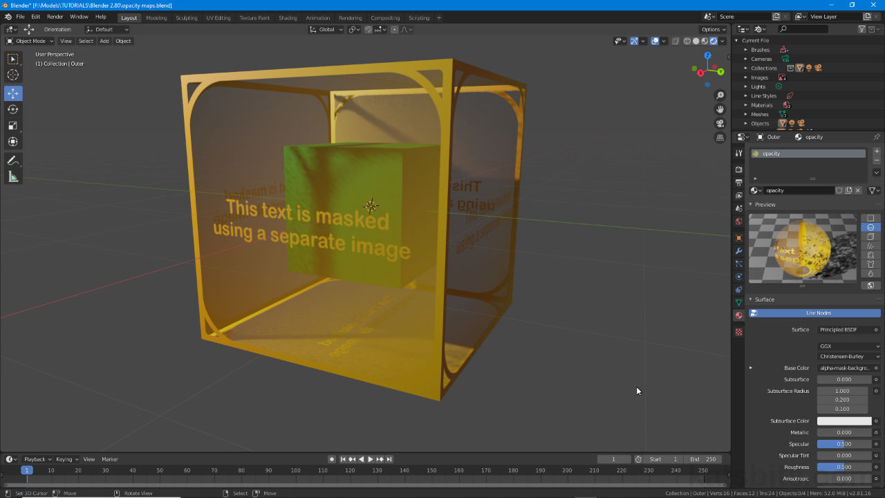
A simple opacity map based transparent material assigned to a Cube rendered in the 3D View using Cycles (note absence of sort-order issues common to Eevee).

Opacity Map vs Opacity Mask
In this context, creating materials that display some degree of image or object transparency, opacity maps, opacity masks, alpha masks, alpha maps et al are all functionally the same in that they provide Blenders node-based material system the data necessary to render transparency using separate instead of inclusive images (i.e. alpha channels). In essence this is done by translating tonal information from an image specifically tasked for the job into transparency values – depending on the type of transparency being rendered, black equates to a surface rendered fully transparent, white fully opaque, grey being degrees of transparency or opacity in between.
Design note: the nomenclature used to describe transparency may differ depending on context, for example black values generally render fully or 100% transparent, which can also be referred to as being none or 0% opaque. In some circumstances this can be confusing, especially so referencing external assets, tools or processes.
Generally speaking then, transparency results from a process that ostensibly filters certain aspects of a material such that content can be seen through it, a cube placed inside another object being visible through the outer objects surfaces for example.

Broadly speaking opacity maps – right, and opacity masks – left (also alpha maps and alpha masks), function the same way, both define areas of transparency or opacity. Masks are typically black and white images, essentially a stencil or cutout, whereas a map might be more complex, offering degrees of opacity, and be fully grey-scale.
Step 1: Basic Material
To set up a transparent material governed by a separate image, first set up an initial but basic Material; (select the object and) in Material Properties click + New to create and populate a new instance if one does not exist. Switch to Shading Workspace and in the Node Editor (lower area) click the Add menu and drop an Image Texture node into the workspace, Add » Texture » Image Texture, then click the nodes Open button [2], browse to and load in a new image, or the Browse Image to be linked button [1] to link an existing (previously loaded) image. Finally click-drag the Image Texture nodes Color output to the Base Color input of Principled BSDF [3].
Design note: once set up the Material will only appear in Material Preview/Rendered display modes if the selected object has been UV unwrapped and mapped.

Set up an initial basic Material by dropping an Image Texture node into the Node Editor once a material is available or assigned, then set the ‘diffuse’ image using Browse Image to be linked [1] or Open [2] to use/load in a bitmap, which is then linked to Principled BSDF [3].
Step 2: Opacity Map/Mask
Once the basic nodes are in place add another Image Texture node, Add » Texture » Image Texture. For this node click Browse Image to be linked or Open the browse to and select/assign the black and white or grey-scale image to be used as the opacity or transparent control element of the material. Once done click-drag this new Image Textures Color output [4] to the Alpha input [5] of Principled BSDF linking the two together.
Design note: a colour image can be used for the opacity map but may cause unexpected discrepancies due to the way Blender converts colour to tone when data is passed through Alpha input. For best results use an appropriate grey-scale or black and white image as required.

To use an opacity map another Image Texture node needs to be placed, the black and white or grey-scale opacity map (bitmap image) then being associated with it, and finally linked (Color output [4]) to the Alpha input [5] of Principled BSDF (near the bottom of the node).
Step 3: Material Settings
Once the materials nodes are set up the final step is to enable or activate the type of transparency or Blend Mode used to render the effect. To do this, with the material still selected, in Material Properties scroll down to Settings (expand the options if not shown) and to the right of Blend Mode [6] click the drop-down menu selecting a ‘type’ from the list, typically Alpha Clip, Alpha Blend or Alpha Hashed. The material will immediately display with opacity map/mask-based transparency.
Design note: generally speaking Alpha Blend and Alpha Hashed tolerate the subtleties of a grey-scale image whereas Alpha Clip does not, it interprets tone relative to being ‘on’ or ‘off’ – black being ‘off’ (fully transparent), white being ‘on’ (fully opaque) – this behaviour can be adjusted changing Clip Threshold if Alpha Clip is set.

Once the nodes are set up and linked together the final step is to set the type of transparency or Blend Mode to use. In Material Properties, under Settings, click the drop-down menu to the right of Blend Mode [6] and select an option, typically Alpha Clip, Alpha Blend or Alpha Hashed. Blender will finally display the transparent aspects of the material.
Video
Overview making a simple transparent material where transparency is defined by a separate image, a grey-scale opacity map or black and white opacity mask.
Blender 2.9+ Opacity
For Blender 2.9+ (and future versions, Blender 3.0, 4.0 etc.) controlling basic material transparency using a separate opacity ‘map’ or image works exactly the same as it does for Blender 2.8+ (explained in detail above), and works in both Eevee and Cycles render engines so long as nodes are correctly linked and an appropriate grey-scale or black and white image is used for the opacity map itself.
Design note: it’s best to use grey-scale images to control opacity as colour can be tonally misinterpreted, ‘red’ for example might result in a darker grey-scale value than expected.
Simply drop in two Image Texture nodes and link Color output from one to Base Color input of Principled BSDF, and the other to the said-sames Alpha input. This will override the Alpha value normally attributed to Principled BSDF, the maps gray-scale values then controlling the degree of material transparency.


Simple material transparency defined by an opacity map requires two Image Texture nodes; one for the image seen, the other holding the grey-scale image that’s to be the opacity map, connected to the Alpha input of the Principle BSDF node.
Basic transparency in Blender 2.9+ defined by a separate ‘opacity’ image (Eevee shown, compatible with Cycles).
