Show Normals
Table of Contents
For Blender 2.8+/2.9+ and newer the way Normals are shown has changed slightly in that the settings are no longer part of what was View Properties. Instead the options can now be found in Overlay.
Design note: with Blender 2.8+/2.9+ objects render doubled-sided by default based on Viewport Shading, culling this to determine which way a surface might be pointing (single-sided rendering) differs as a result. Normals helps in this regard by quickly indicating surface orientation without toggling settings on/off per each mode.
Normals
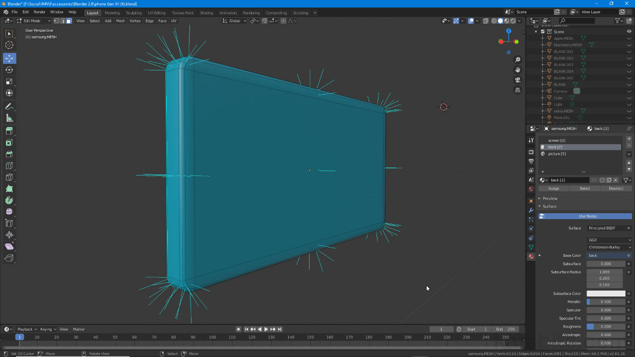
In Blender there are two distinct types of Normal that can be displayed, Vertex and Face, with an ancillary third, Split, indicating these same elements in relation to breaks in surfaces continuity (e.g. as a consequence of Shade/Mesh Smoothing). Normals can be shown as an individual class or type e.g. vertex normals, or in combination with another or all options, e.g. vertex and/or + vace and/or + split. When enabled, Normals are displayed in Blender as a thin coloured line, depending on the type, perpendicular to the element illustrating its orientation relative to neighbouring elements, a flat plain for example, would display a line at 90° to its surface, a subdivided flat plain, several such lines.
Design note: in Blender a Normal generally identifies an averaged XYZ coordinate in 3D space that’s relative to an objects Origin – if an object in Object Mode, or complete mesh in Edit Mode, is manipulated (moved, rotated or scaled) it has no effect on the orientation of a Normal unless the associated element itself, the individual vertex or face, is directly modified or manipulated.

Normals (blue lines) point perpendicular [green] to their respective elements, Vertex or Face [red], indicating the orientation of said element, in particular with respect to its neighbours.
Enable Normals
To activate Normals, select the object or objects in question and switch to Edit Mode (Tab).
Design note: Normals only display in Edit Mode and are shown globally (not selection based).
Here, in the 3D View Header click in the Overlays button upper-right to access the Viewport Overlays drop-down and towards the bottom click the appropriate icon, Display Vertex Normals to show normals for vertexes, Display Normals for faces and surfaces (including Ngons etc.) and/or Display Split Normals to show the orientation of vertex normals that are split (surface continuity breaks). A set of lines will appear coloured dark-blue, pale-blue and pink respectively.
Design note: the length of a normal can be adjusted to accommodate working at different scales, to do this change the Size: value (length is relative to grid scale, the default 0.10 is 1/10th of 1 Unit but may appear longer on some projects that on others due to scale differences, which necessarily prompt higher values to be used, i.e. a line that’s 0.10 in one project might need to be 1.00 to appear the same in another.

To enabled Normals so they’re visible in the 3D View click the Overlay button then set the option in the Viewport Overlays menu – Display Vertex Normal, Display Normals and Display Split Normals.
