Learn Blender – Lettered Game Tiles
Table of Contents
Description
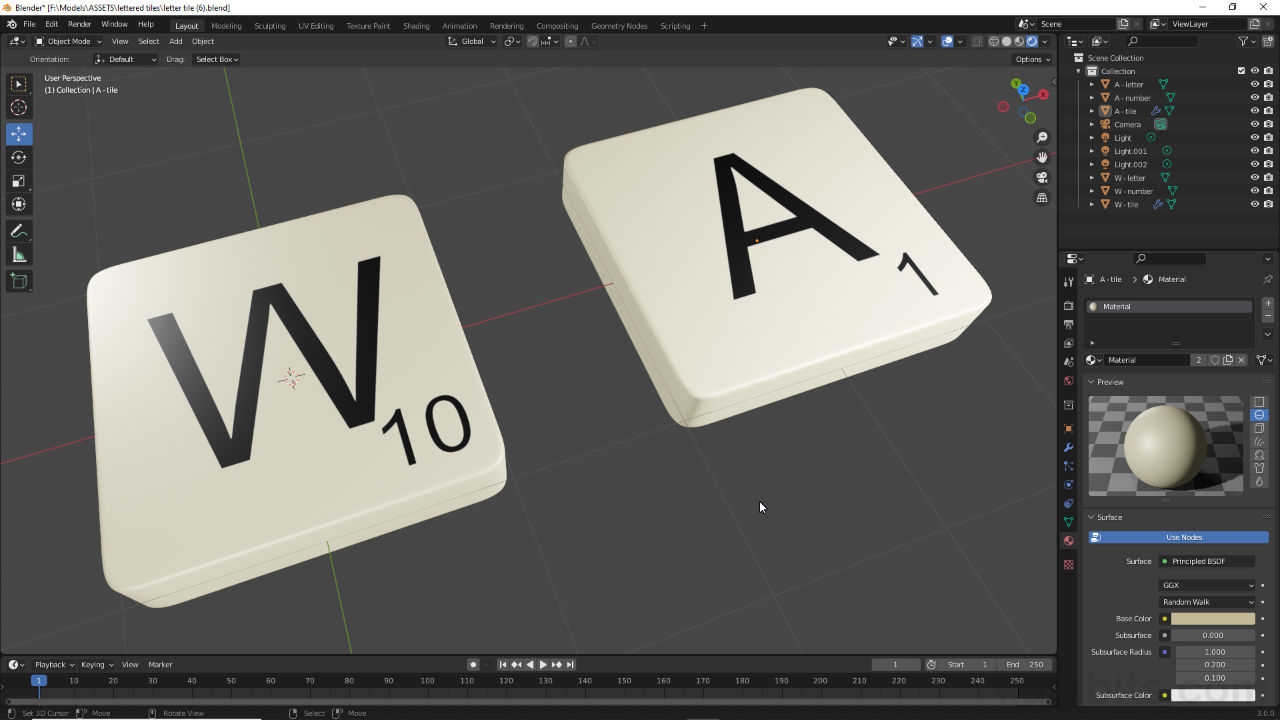
In this simple exercise to learn Blender (compatible with any version) we make a lettered ‘Scrabble’ style tile that can be duplicated to make a set. As with other projects of this type, although seemingly straightforward, the object has to be laid out with a mind for duplication, especially if a full set of letters or game tiles are needed. To this end loop cut is used to control the tiles shape once a Subdivision Surface modifier is assigned, letters and numerical values then being decals that sit above the surface, textured using a sheet.
In part two we look at using the high resolution tile mesh to Bake a normal map that better facilitates the creations of a game-ready version of the tile (and subsequent set). A low resolution version that matches the general structure of the high resolution needs to be made first, which is then assigned a material and UV Unwrapped and UV Mapped before Texture Baking. As normal maps are being used, the letter stencil can also be converted to add a little depth or height to the tile as required.
Suitability: beginners or anyone wanting a simple exercise to get more familiar with Blender (Blender 3.x shown but any version from Blender 2.8x onwards can be used).
Duration: c. 1 hr 30 mins (01:30:00) total.
Info: 1080p | c. 600 MB.
Source: KatsBits – Lettered Tiles (zip c. 3 MB – *.blend, *.psd, *.tga).
Design note: once a Subdivision Surface modifier is assigned, the shape of the tile is largely defined by the distribution of edges and distances between them, in other words, corner curvature or squareness is regulated by altering the distance between the leading edge of a corner [1] and neighbouring edges [2]. In this way different edge and corner styles can be created whilst maintaining the same fundamental shape.
Although Subdivision defines the quality of an object appearance, how that manifests is defined by the underlying structure of the mesh and edge/loop distribution. In this way different styles of corner can be created from different edge [1] and loop [2] layouts.Edge and corner curvature can also be defined using Bevel, either as the Bevel tool [3] or the Bevel modifier [4]. In either case however, they are not as immediately controllable, the Bevel tool for example is selectively assigned and can cause edge collapse, overlap and bad geometry generally, whereas the Bevel modifier typically applies the effect uniformly unless otherwise controlled by the modifier.
Edges and corners can be shaped using the Bevel tool [3] or Bevel modifier [4] but are not as flexible as loop cuts in terms of making adjustments after the fact.Using decals in this context is an effective way to add text to an object non-destructively, i.e. meshes don’t need to fixed, limiting later adjustment or modification, as might be the case using Boolean [5]; text is Line Art and must be converted to mesh data before use, the cut-out effect then being reliant on both text mesh and tile mesh resolution for clean intersection [6], which itself cannot be edited, e.g. material assigned, until the operation is made real (Apply).
Text can be Boolean [5] added or subtracted but this tends to be unpredictable and inconstant based on the shape being used (font design), ‘A’, ‘H’, ‘W’ for example, may create relative clean cut-outs, whereas ‘G’, ‘C’, ‘S’ might not.
The effects attributed to modifiers depends where they appear in the stack panel [6], a Boolean text operation above Subdivision for example tends to result in the operation being affected by whatever sits below in the stack, which can cause issues if meshes need to remain editable.Depending on what the tiles are for they can be grouped using Parent, either to themselves or to a controlling object like an Empty. Simply select each tiles components; tile, letter and number plain – tile can be selected last to make it the ‘parent’ object. Then from the Object menu select Parent, Object – Object » Parent » Object – then in the Make Parent overlay that appears (typically bottom-left), set Object and check Keep Transform. Selecting and moving the tile (or parent object) then moves the group as a whole – this approach to organisation keeps projects manageable because modifiers aren’t applied and meshes are not then displayed in the resource intensive, raw and high resolution form.
Grouping objects informally using Parent rather than fixing object and joining them together using Join means they can be edited later if needed without breaking anything to do so.If the material assigned to the tile is simple, i.e. just a Base Color assignment, the mesh won’t need to be UV Unwrapped or UV Mapped [7] because the property (Base Color) is uniformly applied to the object. Similarly for any of the procedural textures patterns that can be used [8] that rely on the objects physical characteristics, height, width, depth or more broadly volume, rather than the presence of any image mapping.
Without a UV Map [7], two procedural textures, a base color (Add » Texture » Image Texture) and pattern (Add » Texture » Wave Texture) [8], are passed through an RGB Mix shader (Add » Color » Mix RGB) to create a basic textured pattern that’s mapped to the object based on its dimensions or greater volume rather than it having a UVs.For the Bake process to work properly both high and low resolution tile need to be positioned coincidentally, that is, in the same place. This can be checked by selecting each object in turn and looking at their Location coordinates in the Sidebar under View (N) [9], or in Object Properties under Transform [10]. Each needs to use the same X, Y and Z values (location is relative to the Origin of an object, if this differs between the two tiles the coordinates may differ even though the tiles might sit in the same place).
Both versions of the tile need to be in the same location for Bake to work properly. Use Transform data in Sidebar [9] or Object Properties [10] to adjust their position relative to each other.Because Bake utilises the low resolution objects UV layout it’s best to unwrap the the mesh so the overall map uses as much space as possible relative to the image mapped to the object itself. Here UV Seams can be marked across the mesh to selectively split UVs so the map lays out flat with minimal distortion or warping, which will similarly distort or warp the mapped image. In Edge selection mode then, select the edges to be marked and from the Edge menu click Mark Seam – Edge » Mark Seam – to tag the selection which will immediately highlight orange.
Bake relies on texture usage so UVs should be mapped to utilise as much texture space as possible, image-top would result in a baked normal map of lower detailing than image-bottom.Normal maps generated using 2D software, converters and filters often appear inverted because the R, G, and B colour channels are not orientated relative to the 3D application rendering the effect. The fix for this is to ‘swizzle‘ a channel, typically green (G), to realign the image. How this is done exactly differs per application but typically requires a colour channel selection then it being ‘flipped’ or ‘inverted’, in Affinity Photo for example this is done selecting the channel [11] then in the Adjustment panel selecting and applying the Invert filter [12]; in GIMP in the Channels panel [13] select the respective channel [14] then in the Color menu select Invert [15].
Normal maps generated using 2D applications or image converters tend to produce images that require either the green or red channel to be ‘swizzled’ or inverted to correct the orientation of the effect so it renders correctly. In Affinity (image-top) this is done using an Adjustment filter [12], in GIMP (image-bottom) a Color [15] operation.When working with transparency, images that are masked in some way typically exhibit an edge ‘halo’, an artefact of aliasing efforts to smooth text, as in the case, that inadvertently include background colours [16]. Although the type of mask used to render transparency can alleviate the issue to a degree, it has to be dealt with at source, on the image itself. In practice this generally means the diffuse (Base Color) image being a single uniform colour, or the areas immediately surrounding each element has to be expanded to compensate for any bleed [17].
Masked images tend to display a ‘halo’ around masked elements due to aliasing and pixel bleed [16]. To avoid this the diffuse (Base Color) image assigned to the material should consist of a single colour or sufficient colouration to compensate for any leaching [17].


Timestamps
Times are approximate;
Video 1 – High-resolution Tile.
– 00:00 : Overview.
– 00:30 : Tile Meshing.
– 13:00 : Tile Material.
– 18:00 : Image Editing Letters & Numbers.
– 25:00 : Tile Letter.
– 31:00 : Tile Number.
Video II – Normal Maps
– 00:00 : Overview.
– 02:30 : Tile Meshing & Material.
– 09:00 : UV Unwrapping.
– 16:30 : Bake (Rendered) Normal Map (tile).
– 25:00 : Material + Normal Map.
– 31:00 : 2D Converted Normal Map (letters).
