Bake Normal Maps
Table of Contents
Aside from some minor changes, texture baking (or rendering), the process of rendering a high resolution object to a low resolution version, remains largely the same as for previous iterations of the application. However, with the removal of Blender Internal in favour of a Node-based material system, (texture) Bake is now exclusive to Cycles render engine and associated properties.
Bake Normal Maps
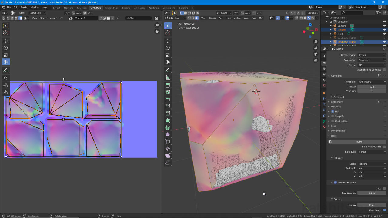
To bake a normal map from a high resolution mesh; in Scene Properties [1] click the Render Engine drop-down menu and set Cycles [2] as the active engine (Scene Properties » Render Engine » Cycles); in the Bake [3] subsection now available (click heading to access options if not visible) click the Bake type drop-down menu and select Normals [4] from the options provided. This readies the project for texture baking normal maps.
Design note: Bake is currently unsupported by the Eevee render engine.

Setting the system up to render texture maps, normal maps in this instance – in Scene Properties [1] first enable Cycles [2] render and then in the Bake [3] subsection set Normal [4] as the type of map to be produced.
Once the system is set up for baking; in the 3D View make sure both high and low resolution meshes are positioned coincidentally, that they occupy the same space. Next, select the high resolution mesh then Shift + click the low resolution mesh to include in the group – the latter outlines brighter orange to confirm selection order. In Bake setting (Render Properties) activate Selected to Active [5] then click the Bake button [6] to rendering the normal map.
Design note: the object selected last is the ‘target’ or ‘active object’, the UV mapped mesh to which normals will be baked. This is generally the low-poly ‘in-game’ item seen by players/users.

Once the system is readied for baking make sure the objects being used are positioned so they occupy the same space then in Bake settings (Render Properties) activate Selected to Active [5] and click the Bake button [6] to begin.

A normal map shown on a low-polygon object rendered using Cycles render engine in Blender 2.8+
Materials & Image Texture
Before using texture bake its important to prepare the object because, using Cycles as the rendering system, materials need to include an ‘image’. In Shading Workspace then, ensure the assigned material(s) have an associated Image Texture node – Add » Texture » Image Texture – linked per a typical node tree, Color output (Image Texture) to Base Color input (Principled BSDF).
Important: bake quality is predominantly defined by image dimensions, a 2048 x 2048 substrate yields 16x the detail of a 512 x 512 image (notwithstanding UV layout). Normal maps should however, generally be rendered to size (size of use).
Design note: for simple texture baking, materials only need an Image Texture node set up as a ‘diffuse’ component for the process to work, it does not explicitly need a ‘normal’ map slot or normal mapped material set up (a material that otherwise takes advantage of the effect) because all that’s being done is rendering something to output (image slot) – the ‘image’ used for this can be internally generated e.g. UV Grid, Color Grid etc., or an externally loaded bitmap image e.g. *.tga, *.tif etc.

To bake a normal map objects need a basic material assigned that have an associated image, internally generated or externally reference bitmap, that acts as the substrate to which the normalised pixel data is written.
UV Unwrapping
For texture baking to work at all, aside from the image assignment required above, objects also need to be UV unwrapped and the respective material image appropriately UV mapped (assigned to the unwrapped UVs) as without, nothing appears on the mesh. How this is done, the form the UV unwrapping takes, depends largely on the object itself, the complexity and/or fidelity of the low-polygon mesh compared to the high-resolution being baked. Whilst UV maps do not affect bake quality per se, they do influence the outcome because they guide the bake process as to where data should be written and how much space is available for that.
Important: UV maps secondarily determine quality based on the amount of UV space dedicated to the object, its features or area emphasis – changing UV’s alters relative texture density, how much UV vs. pixel space/data is given over to each UV, larger UVs equate to occupying more texture space which in turn increase bake resolution or fidelity in those areas.
How UVs are mapped, and the overall UV layout, determines where and how the normal map will bake within the available texture space (size defined by the assigned image). To avoid texture density issues, where some areas appear more detailed than others, UVs should be scaled/sized relatively so each occupies a similar amount of space per what is represented.In addition make sure to provide enough space between UV/islands to accommodate bleed, set via Margin, to avoid edge alising (stepping) issues.
Increase or decrease the Margin value to render bleed that will address aliasing issues that often occur along the edges of baked maps, corners and rounded feature in particular which exhibit ‘stepping’ artifacts.


For texture baking to work objects need to be UV unwrapped as this largely guides the process, where and how the process renders the image, the above for example shows different versions of low resolution ‘cubic’ shape comprising six ‘sides’, or islands, each quite different to their compatriots.
Object Resolution
Bake accuracy, or more correctly bake fidelity, and the success of the ‘normal’ effect in use, depends on how closely the low resolution mesh resembles the general structure of the highly detailed object being baked, essentially how well it summarises the broader features in reduced form. While the degree to which this is done depends on the end use and target technology, allied to UV maps and texture size, low-poly mesh detail can affected bake results quite significantly so a degree trial and error may be necessary to find a happy medium baking normal maps from high resolution meshes to low resolution game objects.
Design note: how low a low-resolution mesh needs to be is generally a problem that’s particular to (in-game) models associated with a set of unique assets, images used only on the object(s) baked. Normal maps baked for use as tiling textures, i.e. models rendered to flat plains, a tiling rock face for example, don’t present this problem, they are not object dependent.

The effectiveness of a normal map is based on how closely a low resolution mesh (right) describes the general shape of the high (left) so some experimentation may be needed to find the right balance between the low resolution mesh and in-game resource use.
Ray Distance
With texture baking essentially being a like-for-like process, both low and high resolution meshes occupy the same space, their proximity can be an issue, especially where surfaces are coincidental and/or clip through one another. Where this happens baked normal maps typically include incorrect colour values that ‘break’ the effect when used. To address this an optional setting is provided in Render Properties, Ray Distance [7], that can be used to correct the problem by increasing the length or distance of the projected rays used to calculate normals. To do this, whilst still in Render Properties and under in Bake settings, increase the value in Ray Distance and render. Adjust until a clean artifact free normal map image is produced.
Design note: when click-dragging the input box to increase the value it locks out at 1.00 m by default unless it has been manually typed, e.g. “25”. Once set this way the slider will then reduce/increase up to that point, e.g. «/» 25″.


The proximity of both meshes can cause problems (top) when baking normal maps (or any texture type) that can generally be addressed changing the Ray Distance value in Bake settings [7] and re-rendering (bottom).
Mesh Smoothing
Using normal maps typically means Smoothing is determined by the high-resolution mesh and the orientation of individual surfaces as represented by the maps RGB colour scheme. Here edge detail or ‘sharpness’ is defined by actual structure rather than simply splitting and edge to create a break in surface continuity. In practice this means both high and low resolution objects should be smoothed for surface continuity purposes, to prevent overt surface faceting, rather than defining detail or structure. To Smooth an object, select it then from the Object menu click Shade Smooth – Object » Shade Smooth. Alternatively, in Edit Mode make a selection then from the Mesh menu click Shading » Smooth Faces – Mesh » Shading » Smooth Faces.
Design note: in Edit Mode smoothing is applied based on element selection, vertex, edge and face; in Object Mode smoothing is applied to the entire object regardless. Click here to read more about smoothing and normals generally.


Smoothing and whether edges appear soft or hard, is defined in the normal map by geometry and normalised colour representation rather than edges/vertices being split apart. Without smoothing normals tend to render as though faceted (top) which should be avoided using Smoothing (bottom).
Swizzle
Due to the way normal maps are used in games and render engines the effect may appear backwards in relation to lighting, shadows and highlight seem inverted. When this happens it usually means the engine environment uses a ‘inverted’ or ‘reversed’ axis on one or more of the maps R (red), G (green) and B (blue) colour channels to that of Blender. The fix for this problem is to flip or invert the offending channel using Swizzle [8].
Design note: ‘swizzle’ or flipping channels can be done in an image editor. When doing this however, be sure to ‘re-normalise’ the result to ensure only ‘normalise’ colours are present in the map else there is risk of rendering artifacts.
To use Swizzle, expand the Influence options in the Bake section if not visible (click heading), click the drop-down for each R, G and B channel as necessary and select/set the appropriate swizzle option to invert that channel, e.g. clicking G and selecting -Y [9] from the list to invert the default +Y, thus flipping the GREEN channel/colours. Re-bake the normal map to apply the setting.


Swizzle allows for a convenient way to flip or invert the R, G and B channels of a normal map at source (during bake) to accommodate render or engine environments utilising different orientation axes for their normal maps than Blender, simply click a channel [8] and select the corrective option from the list [9].
