BSDF & Normal Maps
Table of Contents
As with other aspects of Blender 2.8’s node-based material system, the changes and improvements also affect how materials make use of normal maps, the external bitmap/image variety common to game or content creation. To function properly, a dedicated Normal Map node has to be used as part of a larger material node-tree, that once set up, results in a material that responds correctly to real-time lighting and Scene illumination.
Download: example node based normal map material *.blend (c.2 MB).
Important: Blender may use different RGB colour orientations for normal maps than other real-time game or rendering engines which might mean the red and/or/both green colour channels (blue is typically unused in this context) being ‘flipped’ or inverted in an image or photo editor for proper functionality. For more help with this see ‘How NOT to make Normal Maps‘.
Normal maps used in Blender may need to be be ‘channel flipped’, i.e. the red (left/right) or green (top-bottom) colour channels inverted so the normalised effect works correctly in response to dynamic/real-time lighting.


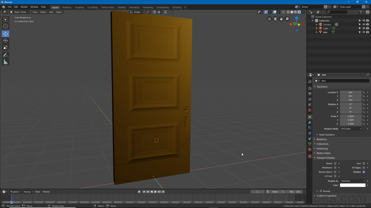
A door textures that’s been modified to accommodate use of a normal map (courtesy of Return to Castle Wolfenstein) exhibiting per-pixel shading effects as a light source moves in relation to the object.
Standard Material
Normal maps generally don’t work on their own (unless used as both ‘normal’ and ‘colour’ components of a material) so a standard or basic material will first need to be created to hold a ‘diffuse’ or ‘color’ image. To do this, select the object in question and click the Material Properties button. Here create a Material instance (or select if available) and assign to the object (auto-assigned if object is selected beforehand). Ensure Use Nodes is enabled, switch to Shading Workspace and add an Image Texture node (Add » Texture » Image Texture). To this create a + New texture or Open a preexisting image, e.g. door.tga, and then link Color output [1] to Base Color input [2] – Image Texture to Principled BSDF. This creates a basic material that will appear in the 3D View (upper section of Shading workspace).
Design note: some materials won’t appear on the mesh, or correctly orientated or positioned, unless the object being textured is UV unwrapped and mapped, in the example shown below, to the Image Texture node associated with the standard material described above.
Creating a basic Material aids objects being properly UV unwrapped and mapped. Without this nothing appears on the mesh when the material is completed or assigned.


Normal maps generally don’t work without other components of a Material being present so they need to be generated first, a basic node tree that contains a Texture Image node [1] will suffice (shown above as a flat brown for clarity) that’s linked to the Principled BSDF node [2].
Normal Map Node
With a basic material set up to include normal map functionality, in the Node Editor add a Normal Map node from Add » Vector » Normal Map [1]. This will drop a new node into the workspace, Normal Map [2] (the nodes header will be purple indicating its association with Vector based functionality). Check the Space is set to Tangent (or appropriate setting per intended use – default is Tangent).
Design note: make sure to select Normal Map not Normal, the two nodes are different.

Once a basic material is available add a Normal Map node to the workspace from Add » Vector » Normal Map. Set Space to Tangent (or appropriate option per intended use if not already set – ‘Tangent’ is the default).
To this, from Add » Texture » Image Texture, place another Image Texture node [3], load in (click Open) the RGB normal map image (bitmap) that’s to be used as the materials normal map, then set Color Space to Non-Color Data [3].
Important: Non-Color Data essentially nullifies the normal maps intense RGB colours influencing the materials final (diffuse) appearance – without this setting normals can appear broken or incorrectly lit.
Once the Image Texture node is set up, link Color output [3] to Color input [4] connecting Image Texture and Normal Map nodes together, then Normal output [4] to Normal input [5] linking Normal Map to Principled BSDF. This activates the normal map so the effect, per-pixel shading, displays on the object in the preview area.
Design note: depending on the diffuse (‘Color’) image assigned to the material, the normalised effect may not be readily apparent (cf. How NOT to make normal maps). To compensate for this increase the Strength value (default 1.000) attributed to the Normal Map node, larger values equal stronger effect (the slider maxes out at 10.000 but higher values can be manually typed).
Increasing the Strength of the normal map to make the effect more pronounced.


Once an Image Texture and Normal Map nodes are available they can be linked together and then to Principled BSDF (via the Normal Map node) to form a node chain (branch) that complete the material tree. Subject to other elements of the material, the normal map effect will then display in the 3D View.

A door mesh object, little more than a six sided door-shaped cube (six polygons total and mapped a flat colour for clarity), appears with structural detailing that’s provided solely by the assigned normal map (without the object appears as a flat object), it reacts in real-time to changes in scene lighting as a result.
