Texture Blending using Vertex Colour (Simple)
Table of Contents
An alternative approach to Texture Blending using Masks several materials, textures or images together is to use vertex colour blending. Here, different textures are associated with a specific vertex colour that can be painted over a mesh, wherever colour appears so too the corresponding material, texture or image, giving the appearance of blending, one image to another.
Prerequisites
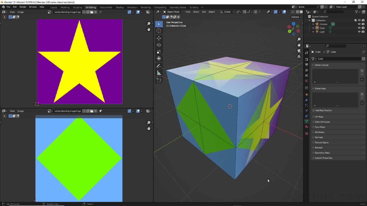
Before using vertex colour based blending the object(s) to be affected should be appropriately UV unwrapped from within UV Editing workspace, and assigned a basic material [2] in Shading workspace. An image [3] (Texture Image node with either linked or Generated image data) should be associated with the material and mapped across the objects surface as would normally be done when texturing something. This is the initial material blending will mix with, and mapping used to display the result over the mesh.
Download: Katsbits – Vertex Blend Textures (c. 300KB | *.blend, *.tga).
Design note: vertex colour defines the mix between materials and their position relative to the mesh – wherever colour is painted textures will blend. How the effect then looks relies on the object being unwrapped and underlying image(s) properly mapped across its surfaces. In other words, blending can be done independently of UV mapping but the images involved may appear distorted or malformed if their UV mapping is similarly distorted or malformed.
Important: images will generally need to be the same dimensionally to avoid, for example, distortions cause by mapping a rectangle to a square UV – images can be of differing size, e.g. 512 x 512 blending with a 1024 x 1024, but not differing dimensions, e.g. 512 x 256 blending to a 256 x 1024.In addition, while UV maps define placement across a mesh, its structure or density play an equally important role in that colour can be painted to individual vertices more precise only so far as the mesh’s density or structure accommodates – the denser or more complex a mesh the better or more accurately colour can be painted, and subsequently, textures blended.
Mesh structure and/or density affects how vertex colours distribute across a mesh once painted, and subsequently, how accurately textures blend and conform to the objects shape.


It’s best to UV unwrap and fully UV map [1] objects before using vertex colour blender so the effect can be properly understood relative to how it should appear on the mesh.

The initial material assigned to the object [2] should have an Image Texture node [3] associated with it linked to bitmap or Blender generated data.
Mix Material
Once the basic material is in place the next step it to modify the node tree to add the second blending image that’s to be mixed with the first, and the means by which that is controlled. To do this, first drop in a new Image Texture [4] node – Add » Texture » Image Texture – and externally link to, or generate, an image (green diamond shown below). This will be the image used for blending. To this drop a Mix Color [5] node – Add » Color » Mix Color – and a Color Attribute [6] node – Add » Input » Color Attribute.
Important: as of Blender 3.2 the Vertex Color node is obsolete and has been replaced by the Color Attribute node.

To the Basic material an additional ‘blend’ image [4] needs to be included alongside and Mix Color [5] and Color Attribute (formally Vertex Color) nodes.
With the new nodes available they need to be linked together as follows; link Color output of the second Image Texture node to B input of Mix Color [7]. Then link Color output of Color Attribute to Factor input of Mix Color [8] – both the Image Texture and Color Attribute nodes should be linked to Mix Color;
– Image Texture | Color » B | Mix Color
– Color Attribute | Color » Factor | Mix Color
Design note: linking material nodes together can be done at any point but is performed here for sake of context and clarity.

The new nodes need to be linked together, Image Texture and Color Attribute connect to the B [7] and Factor [8] inputs of Mix Color respectively.
The final step in setting up the material is to then link the original Image Texture node to the ‘blend’ node group and connect that to Principled BSDF as the overall output of the collection. To do this connect the Color output of the original Image Texture to the A input of Mix Color [9], then connect its Result output to the Base Color input of Principled BSDF [10]. Although the nodes are now correctly connected the 3D Viewport will continue to display the original texture mapped to the object.
Design note: disconnect the original Image Texture from Principled BSDF.


The blend material is incomplete until the original Image Texture node is linked to the Mix Color [9] node, which is in-turn, connected to Principled BSDF [10].
Vertex Colour Painting
At this point the materials node tree is set up but is not yet referencing any vertex colour data. For that, in the 3D Viewport select the object to be painted and switch to Vertex Paint [11] mode – the mesh may change its appearance to be mapped with the ‘blend’ material which confirms the material is referencing the correct vertex colour data block (accessible in Object Data Properties » Color Attributes). Set the vertex colour to be painted [12], typically black or white depending on material set up, and paint across the surface. Wherever the vertex colour is painted [13] the materials will blend [14]; black blends out Image A for image B, white blends out Image B with Image A, and grey blends both Image A and Image B together.
Design note: at this point materials will blend as soon as vertex color is painted to the mesh so there is no specific need to reference the vertex colour’s data block within the Color Attribute node. This function can however, be used to force the use of particular vertex colour data blocks, which then ignores any others that might be present. To do this, make sure the object is selected in the 3D Viewport and while the material node tree is accessible in Shading workspace, switch the Properties panel to Object Data Properties [i]. Here, expand the Color Attributes subsection (formally Vertex Colors) and click the + button [ii]. The Add Color Attribute [iii] context pop-up will appear. Give the new datablock a Name to distinguish it from other blocks and, for vertex colour blending, ensure Domain is set to Vertex, and Data Type is set to Color. The Color sampler can be left black (default), or changed to the vertex colour that’s to be associated with the datablock – white then typically becomes the ‘opposite’ colour that’s blended to/with. Click OK. In the Color Attribute [iv] node set the (new) datablock as the group to reference.
Although not specifically needed for vertex colour blending to work, a Color Attribute can be set so the material references a particular vertex colour datablock. First create the block [i-iii], then set it as the reference in the Color Attribute [iv] material node.


Once the blend material is set up, in the 3V Viewport (or other appropriate view where vertex colours can be painted) switch to Vertex Paint [11] mode…

… set or select the vertex colour to be painted [12] – for simple blending this will be black, white or shade of grey depending on the degree of mixing…

… and paint over the mesh. Where the vertex colour (black) is painted Material A [13] appears, where the default colour (white) remains, Material B [14] appears.
Preview Vertex Colours
To fully monitor the blending process, both material blending and vertex colour painting, the underlying material [15] will need to be modified to include another Color Attribute and Mix Color node group [16].
Design note: enabling the display of vertex colour may obscure underlying materials and/or blending.
First decouple the initial group from Principled BSDF – click-drag the Mix Color’s Results output connector away from the Base Color input. Next, drop in another (or duplicate the existing) Color Attribute node – Add » Input » Color Attribute, and a Mix Color node – Add » Color » Mix Color.
Design note: ordinarily vertex colours are only visible in Solid display mode when Vertex Paint mode is active.
With these new nodes; connect the Color output of Color Attributeto the A input of Mix Color; the Results output of this same node to Base Color input of Principled BSDF; and change the blend mode from Mix to Multiply [17]. This will display just the vertex colours. To then show any texture blending; connect the Results output of the first group’s Mix Color to the B input of the second group’s Mix Color and set this nodes Factor value to 1.000 [18]. Both texture blending and vertex colours will then display on the mesh.

To display vertex colours in Material Preview or Rendered modes a new sub-group [16] need to be added to the original [15] that includes another Color Attribute and Mix Color node. These are linked together, with the original passing through this new group…

… which then has the ‘blend mode’ changed from Mix to Multiple [17], and the Factor value set to 1.000 to show both material blend and vertex colour data.
Edge Orientation
As with anything to do with vertex painting it’s important to understand how edge orientation influences the way blended materials might be distributed across a surfaces due to the way colour, and subsequently blends, bleed along edges. In other words, the distribution of a blend will change depending on edge flow, a rotated diagonal edge for example, will re-orientate a blend, which in-turn may change the appearance or characteristics of the effect. This issue might be more noticeable using patterns than it might organic or noisy images.

Shown above vertex colour (black) highlights how blended materials might change based on the orientation of edges across the mesh.
