Rig & Animate a Game Asset (Gate/Door)
Table of Contents
Description
In this exercise we take a look at animating a simple medieval style gate in Blender using an Armature to rig and animate the object with a focus on what needs to be kept in mind when doing so. First, the object has to be prepped for animation so it pivots or rotates correctly around its origin and, optionally, edited to prevent gaps and wholes that might occur when animated. An Armature is then added and various bones extruded to set up a skeletal hierarchy that controls the mesh using Vertex Groups before everything is then animated in the Action Editor.
Design note: some additional considerations to keep in mind for simple animated objects that don’t deform, i.e. ‘furniture’, environment assets and so on;
Origin as Pivot
As a general rule of thumb, when prepping a mesh for animation, preference should be given to positioning objects [1] relative to their Origin point [2]. While this is not crucial – the location, rotation and scaling of objects, how they move or deform, is relative to bone influence – it can be helpful with workflow if both Mesh Origin and Armature Origin both match. Adjusting or modifying an objects Origin can be done in Edit Mode [3] or Object Mode by moving everything relative to the Origin [4], or moving the Origin relative to the object.
For more on repositioning, adjusting or correcting the location of a mesh relative to its Origin, or adjusting the Origin relative to the mesh, see “(Re)Set Origin“.
Gate shown with mesh ‘incorrectly’ positioned [1] relative to the objects Origin [2]. To aid rigging and animation, especially where something pivots or rotates around a fixed point, objects should be positioned relative to their Origins.
Changing the object in Edit Mode [3] by moving the entire mesh into position relative to the Origin [4], which aligns the object with the pivot point.Grid Centre
Unless objects are to be animated in situ, positioned as part of a larger scene, they should be located at grid centre – X: 0.000, Y: 0.000, Z: 0.000 (0,0,0) [5]. Generally, this is done to prevent an offset being saved to the project file during export that may be, inadvertently, used when imported in to other sources. This should be done before rigging with Armature and animating. To do this, with object selected, in the Item [6] tab of the Sidebar (N), zero-out the X, Y and Z values under Location, or similarly in Object Properties [7].
Object location is defined relative to the selected objects Origin so a mesh may appear offset even though it’s correctly placed relative to the grid. In practice, make sure mesh and object Origin are properly positioned with respect to each other.
To avoid problems when animating, and on import into other sources, it’s best to position objects relative to grid centre [5]. This can be done using XYZ Location data in the Sidebar [6] or similarly Object Properties [7].Armature & Bone
When adding an Armature to a scene Blender defaults to placing them at the location of the 3D Cursor. With this in mind, if mesh or Armature needs to be moved or realignment with respect to each other, this should be done before completing the rig or animating to avoid issues. With this in mind, move the 3D Cursor to where it needs to be [9], typically snapped to the selected object, and once placed – Add » Armature [8] – use the transform tools, Move and Rotate in particular, to position the Armature [10] relative to the mesh, or move the mesh relative to the Armature.
Important: an objects Origin defines where objects are located, rotated or scaled in relation to 3D space and grid centres – all coordinate systems have a 0,0,0 grid centre. Origins also determine how objects generally are positioned relative to each other.When moving objects, meshes or Armatures, ensure this is done while in Object Mode unless repositioning the selection relative to its own Origin.
Blender positions Armatures at the 3D Cursors location, so once added [8] it may need to be moved [9] to align with the object its going to animate [10], e.g. at grid centre.Vertex Groups
Where an Armature and its bones are the mechanism of control, Vertex Groups are the link between the two. Here, naming and labels are critical as they need to correspond with bone names to create the association needed for the Armature know what part of the mesh each bone is supposed to articulate [11]. To this end the default name “Group[.n]” can be changed in Object Data Properties by changing the label in the Vertex Groups list [12]. To do this double-click an entry and type. Alternatively, in the Outliner select the mesh and under the Vertex Groups subheading [13] similarly double-click an entry and type.
Important: because Vertex Groups create the link between mesh and bone, labelling needs to match exactly, “handle” is not the same as “Handle“.There a number of ways to ‘rig’, that is match the mesh to bones in the Armature. For example, while selected areas can be manually assigned to different Vertex Groups in Edit Mode, the same can be done using Envelopes when Parenting, or using Weight Paint mode to paint bone influence as colour.
Meshes are controlled by bones [11], which are linked using Vertex Groups. It’s crucial therefore, to ensure corresponding groups and bones match names or labels, which can be changed in Object Data Properties [12] or the Outliner [13].Auto Keying (Insert)
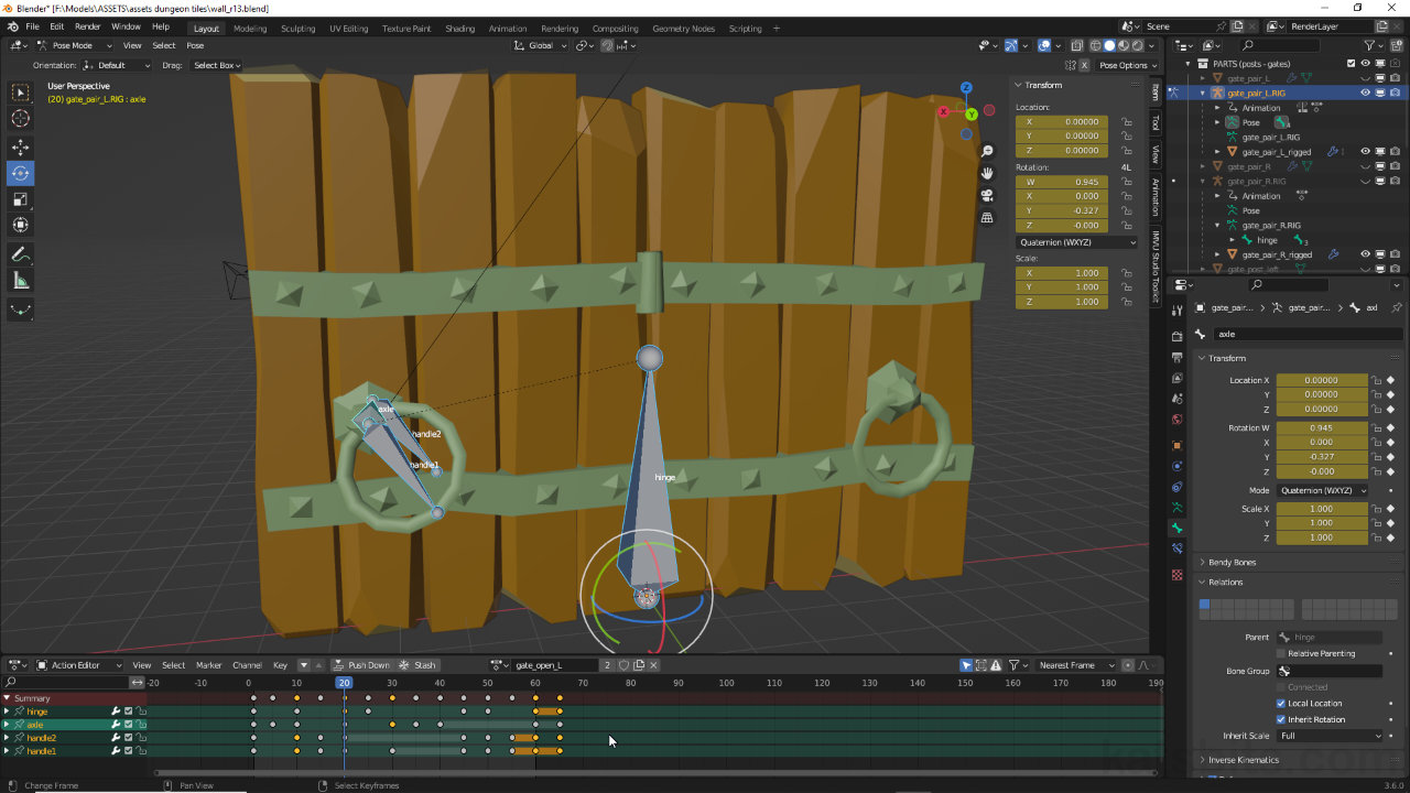
Keyframes generally have to be manually placed in the timeline using Insert (I), which can be repetitious for long or complex sequences. To alleviate this Blender can be set to insert keyframes automatically whenever it detects a bone or object has been moved or manipulated in some way. This is done using Auto Keying, which drops a keyframe or pose marker into the timeline that saves all, or specific, types of coordinates data, typically Location & Rotation (LocRot) or Location, Rotation & Scale (LocRotScale).
Important: the Auto Keying and playback buttons (transport controls) are only accessible from the main Timeline editor Header.To enable, in the main Timeline editor click the record or Auto Keying [14] button in the Header, then in the Keying menu [15] set the Keying Type, the type of data saved to the timeline, by clicking the Active Keying Set input field [16] and selecting an option from the list, e.g. Location & Rotation to store linear and rotational movement – Keying » [Keying Type] » [option]. Switch back to the Action Editor and pose the Armature, with Auto Keying enabled any bone poses will be automatically marked in the timeline at the scrubbers location.
Playback functions can be activated from within other editors using the following shortcut keys;Windows OS
Space – Start/Stop
Shift + Ctrl + Space – Play Reverse
Up Arrow (↑) – Next Keyframe
Down Arrow (↓) – Previous Keyframe
Shift + Left Arrow (Shift + ←) – Jump to Start
Shift + Right Arrow (Shift + →) – Jump to EndMacOS
Space – Start/Stop
Shift + Command + Space (⇧ + ⌘ + Space) – Play Reverse
Up Arrow (↑) – Next Keyframe
Down Arrow (↓) – Previous Keyframe
Shift + Left Arrow (⇧ + ←) – Jump to Start
Shift + Right Arrow (⇧ + →) – Jump to End
Enabling Auto Keying [14] will automatically save bone data to the Timeline. This can be set [15] to save a specific data ‘set’ [16], typically Location, Rotation & Scale.


![[descriptive alt image text here]](https://www.katsbits.com/images/tutorials/animation/timeline-keying-set.jpg)
Timestamps
Times are approximate;
– 00:00 : Overview & Object Setup
– 04:30 : Armature & Rig Setup
– 13:00 : Mesh Setup & Vertex Groups
– 22:00 : Mesh Adjustments
– 36:30 : Action Editor & Animation
– 51:30 : Summery
