3D Printing & Blender – USB-C Sleeve (Accuracy in Printing)
Table of Contents
Description
In this exercise we take a look at modelling and then 3D printing a sleeve or shroud that fits over the broken housing of a USB-C power adaptor (Dell WD15 Docking Station). Before starting, Blenders units of measurement is set to millimetres ensuring a 1:1 correlation with the 3D printing environment. Once done the adapter housing itself is then shaped as a template, a simple solid mesh that describes the physical dimensions of adapters outer housing. Next, the initial shape for the sleeve is modelled using the housing template as a guide. This is then duplicated and ‘thickened’ before being prepped and exported to *.stl, then further prepared and exported to *.gcode for 3D printing using a slicer.
Duration: total c. 40 mins (00:40:00).
Info: 1080p.
Suitability: Beginner+.
Source: n/a.
Product ID: n/a.
Print Info: c. 30 mins print time | c. 1m FDM used.
Design note:additional considerations when modelling something in Blender for 3D printing objects that necessitate a degree of dimensional accuracy;
Units of Measurement
For successful 3D printing where precision is required, projects should be set up to mirror the printers environment before modelling begins. Typically this means setting Blenders Units system to millimetres, with a grid scale to match. To do this, in Scene Properties, access Units and set Length to Millimeters with a Unit Scale of 0.01 [1]. Once set, in Viewport Overlays [2] set the grids Scale to 0.01 [3] matching Unit Scale.
[image caption here.]Face Fill
Where new structure has to be manually added, for example using New Edge/Face from Vertices [4] (Fill) – Edit Mode: Vertex » New Edge/Face from Vertices – to close gaps and holes, to do this effectively there needs to be a physical relationship between the area or selections being filled. In other words, selecting an outer (pink) and inner (yellow) [5] edge loop to fill between the two won’t work because they are not connected or linked together in any way, resulting each edge loop being filled independently from the other, completely closing off the end of the shape. To avoid or mitigate this issue, an individual face can be created using a smaller selection [6], which closes the edge loop [7], that can then be filled correctly [8].
Filling an ‘open’ face [4], i.e. are area only linking to itself results in the entire face being filled because there isn’t a connection between any others [5]…
… whereas filling a single face [6] essentially closes the edge loop allowing it to be selected and filled properly [7] because everything is now linked or connected.Thickness/Solidify
Using the Solidify modifier is a simple way to make a plain or simple surface thicker. However, similar to using the Subdivision Surface modifier, a number of considerations should be kept in mind when doing so;
- Mesh thickness: once applied the Thickness [9] attributed will be limited to the 3D printers minimum capabilities. In other words, mesh thickness is restricted to the thinnest line that can be successfully extruded absent plate adhesion issues by the 3D printer – although the extrusion nozzle of a 3D printer might be 0.2mm it may not be capable of producing a 0.2mm line due to the nature of the medium and the printing environment.
- Dimensional shrinkage: the way the Solidify modifier works it may inadvertently introduce some dimensional shrinkage [10] that could cause issues when printing, especially where accuracy is wanted (see yellow boxout below).
- Modifier Stack: the modifiers position the modifier stack may negatively affect the effect; placed before Subdivision Surface for example, the result is very different being much thinner and without the edge definition afforded by structural smoothing.
The Solidify modifier [9], like other ‘generative’ modifiers, can negatively affect a mesh [10] when applied. If so, some corrective edits may be necessary to compensate.Subdivision Distortion
Adding a Subdivision Surface modifier is a useful way to generate a high-resolution version of a mesh. In doing so however, be aware that this may change the physical structure of the mesh such that it is no longer dimensionally correct. In other words, the way the subdivision algorithm works it may tend to shrink structure [11], especially where curves are expected, in ways that might not be fixable by simply adding more loop cuts [12] or other structure. While advanced construction techniques can be utilised to compensate for this, the most straightforward solution in this context, of 3D printing using FDM or other extruded and layered materials, is trial and error fit testing and adjustment is the most practicable approach.
Important: when modelling something that’s meant to be used with another object, a certain degree of ‘fit testing‘ or trial and error is be expected. In other words, although measurements may be dimensionally correct in terms of an objects physical representation in Blender, the inherent nature of 3D printing, and mediums like FDM, mean there’s enough variability that exact 1:1 replication of model might not be immediately or initially possible. For example, while a 3D printers nozzle might be 0.2mm, when printing, the medium might spread, resulting in a line that’s actually 0.5mm, 2X the nozzle spout. Under these circumstances it may then be necessary to adjust models in Blender to compensate in ways that make them dimensionally incorrect as 3D objects but functionally or pragmatically correct for 3D printing. These types of adjustments can only be done through trial and error.
Three different versions of the same object adjust and 3D printed for ‘fit testing’ – the nature of using Blender, and 3D printing itself can cause issues that might require adjustments to compensate for.
Subdivision typically shrinks structure due to the way it works [11] that might not be fixable by just adding loop cuts [12], and instead by manually adjusting the mesh to compensate for any dimensional losses.Object Prep
As a format, STL is similar to FBX in that objects are exported from Blender in situ, that is, wherever they are positioned or rotated in the scene. This is useful because it allows multiple objects to be pre-arranged in Blender and exported to the same STL file for final gcode prep in a slicer. However, while this is possible it may cause issues, particularly as might relate to object position within a group being optimal for 3D printer. Where possible preference should be to export objects separately and let the slicer arrange them for printing.
Important: depending on what an object is being 3D printed for, some adjustment may be necessary in Blender to accommodate artefact clean up, that is sanding, filing, smoothing or otherwise removing surface and structural inconsistencies that result from 3D printing, FDM in particular. While doing this care should be taken to ensure the core structure of a model remain unaffected, in other words, additions should be added or extruded from existing structure [i] rather than changing that structure.
A tolerance [i] may need to be added to the model in Blender to accommodate clean-up of the eventual print, espcially when using linear mediums like FDM.
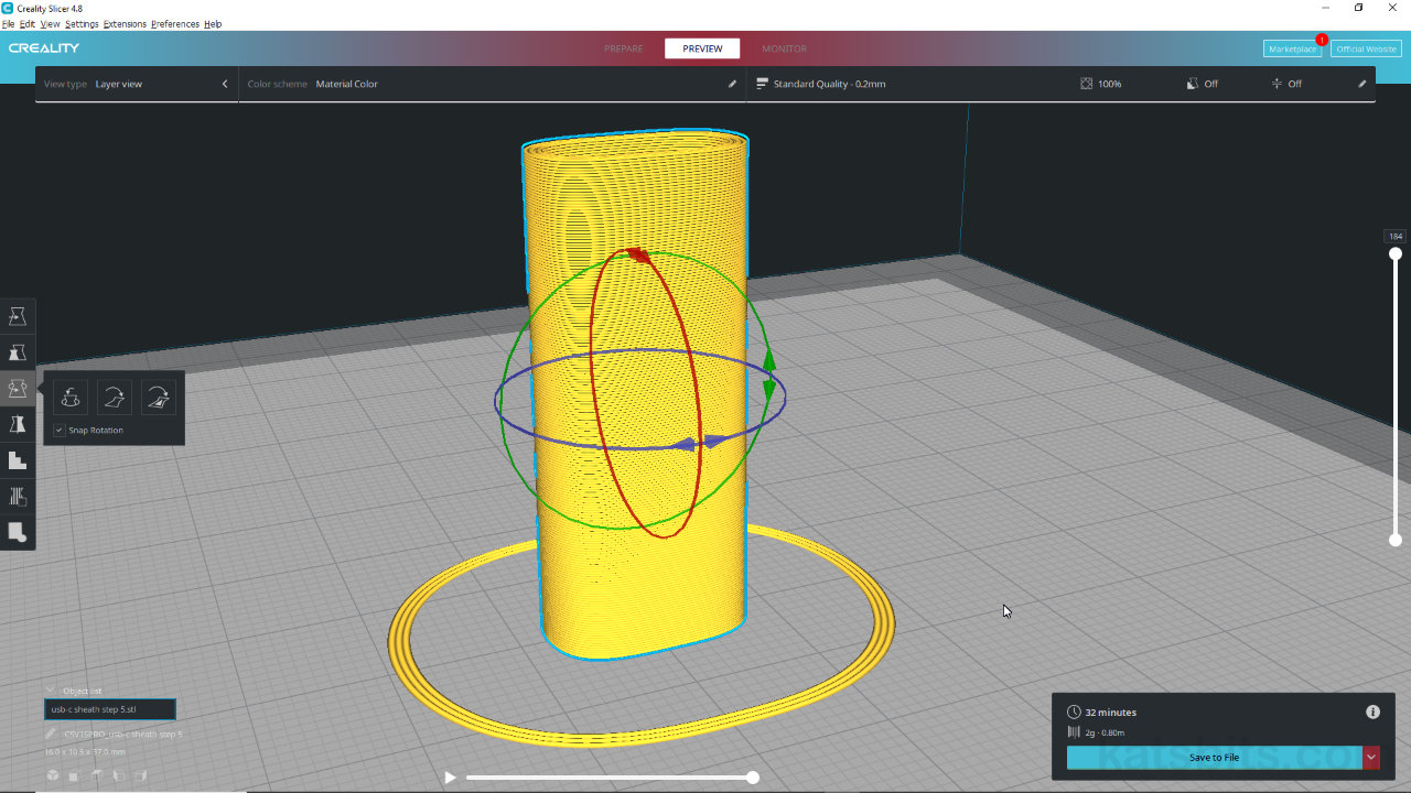
Image-top: a collection of objects imported into a slicer that have been prearranged in Blender and exported as a group – note the issue with the initial track intersecting the object. Image-bottom: the same objects imported individually into the same slicer and automatically arranged.
![[descriptive alt image text here]](https://www.katsbits.com/images/tutorials/3d-printing/scene-scale-setup.jpg)


![[descriptive alt image text here]](https://www.katsbits.com/images/tutorials/3d-printing/clean-up-tollerance.jpg)


Timestamps
Times are approximate;
– 00:00 : Overview & Project Setup.
– 05:00 : Block out & Shaping.
– 09:00 : Adaptor Template.
– 12:30 : Outer Sleeve.
– 19:00 : Solidify Modifier.
– 25:00 : Export Prep & STL Export.
– 30:00 : Slicer Prep & Export.
– 34:00 : Addendum.
