Blending Multiple Textures using Vertex Color
Table of Contents
Using vertex colours (vertex colors) to blend textures and/or materials is relatively straightforward to set up for simple mixes that only involving two textures. Where three or four are needed, the material node tree has to be modified to accommodate, and then blend together, each additional image. This is done largely though interlinking Mix Color and Separate Color nodes.
Download: Katsbits – Vertex Blend Multiple Textures (c. 500KB | *.blend, *.tga).
Prerequisites
Before material setup, meshes generally need to be fully UV unwrapped and UV mapped with respect to how the final mix is to be shown across the objects surfaces. In other words, a UV map of some description is necessary for materials to render on surfaces as well as their being correctly positioned and distributed (for game related content specifically).

For texture blending to work correctly generally, objects need to be fully UV unwrapped and UV mapped.
Basic Blend Material
For sake of clarity, the blend materials initial state can be to mix two textures together. In Shading Workspace (or the Node Editor), and to a standard material (Principled BSDF and Material Output), drop in two Image Texture nodes [1] (Add » Texture » Image Texture) and load in, or create, the images to be mixed together. To these add a Color Attribute node [2] (Add » Input » Color Attribute) and Mix Color node [3] (Add » Color » Mix Color).
Important: circa Blender 3.4, MixRGB has been relabelled Mix Color.
Design note: for more on setting up the initial blend material see “Texture Blending using Vertex Colour (Simple)“

Set up a basic ‘blend’ material first by adding two Image Texture nodes [1], a Color Attribute node [2] and a Mix Color node [3] (the object will initially appear white indicating a material has been assigned without image data throughput).
Next, link the nodes together. Connect the Color outputs from both Image Texture nodes, one to the A input, the other to the B input of Mix Color [4];
Image Texture #1 | Color » A | Mix Color
Image Texture #2 | Color » B | Mix Color
Connect the Result output from Mix Color to Base Color of Principled BSDF [5];
Mix Color | Result » Base Color | Principled BSDF
Finally link the Color output of the Color Attribute node to the Factor input of Mix Color [6];
Color Attribute | Color » Factor | Mix Color
If the mesh has been appropriately painted with vertex colour (black or white), the textures referenced in the material will appear blended based on where that colouring has been painted. If the mesh has not yet been vertex painted the image associated with the A input of Mix Color will be rendered.
Design note: the inclusion of Principled BSDF accommodates other shader effects; Sheen, Metallic, Specular, etc.

The Mix Color node acts as a passthrough for the other nodes where they are mixed or blended together; Image Texture nodes connected to the A and B inputs, Color Attribute to Factor.

When nodes are correctly connected, and object vertex colour painted, the images referenced by the material will appear blended together based on where vertex colour has been painted.
Multiple Textures
To blend additional textures, up to four in total using this approach to texture blending, similar to the previous set up described above, drop in the requisite Image Texture nodes [7] and load in or generate a corresponding image. For each of these new image nodes add an accompanying Mix Color [8];
Design note: if the original Color Attribute and/or the Mix Color nodes are still linked through to Principled BSDF disconnect them for ease of set up – the object will render white, again indicating a material assignment absent image throughput.
(Image Texture #1
Image Texture #2 + Mix Color #1)
Image Texture #3 + Mix Color #2
Image Texture #4 + Mix Color #3
Connect the Color output for each additional Image Texture node to the B input of the corresponding Mix Color node (object will appear/remain rendered white);
Image Texture #3 | Color » B | Mix Color #2
Image Texture #4 | Color » B | Mix Color #3


To blend more than two images, drop in one or two more Image Texture nodes [7] and a corresponding Mix Color [8] node for each. These need to be linked, Color outputs of the former, to B inputs of the latter (initial node disconnected and Color Attribute removed for clarity).
Mix Color Chain
Once the images are connected to the Mix Color nodes B inputs, link the Result output [9] from each Mix Color node to the A input [10] of the following Mix Color node, the last being connected to Base Color input of Principled BSDF creating a chain between the set;
Mix Color #1 | Result » A | Mix Color #2 | Result » A | Mix Color #3 | Result » Base Color | Principled BSDF
Design note: absent vertex colour painted on the mesh, images will appear uniformly blended as one.


Once the images are set up they need to be linked in a chain through to Principled BSDF by connecting each Result outputs [9] to the following A inputs [10] of the Mix Color nodes.
Separate Color
With any additional images in place and linked through to their respective Mix Color nodes, add a Separate Color node (Add » Converter » Separate Color). To this, connect Color output of the available Color Attribute node (add this is not available – Add » Input » Color Attribute) to Color input of Separate Color [11], and set Mode of color processing to RGB [12];
Color Attribute | Color » Color | Separate Color
Important: circa Blender 3.4 Separate RGB was renamed Separate Color.

To prepare for mixing drop a Separate Color node into place and link the Color output of Color Attribute to its Color input [11], then set the ‘mode’ to RGB [12].
Finally, to activate blending, link the Red, Green and Blue outputs [13] of the Separate Color node to the Factor inputs of the Mix Color nodes [14], one R, G or B colour channel per mix node input;
Separate Color | Red » Factor | Mix Color #1
Separate Color | Green » Factor | Mix Color #2
Separate Color | Blue » Factor | Mix Color #3
Design note: the Red, Green and Blue outputs can be mixed-and-match to the Factor inputs in any order so long as one channel is linked per node, doing this simply changes how textures are then blended together.


To active the blending function of the materials the Separate Color outputs [13] need to be linked to the Factor inputs of the Mix Color nodes [14], one channel per mix node (absent any vertex colours painted to the mesh the first image linked to the A input of the first mix node will be shown).
Vertex Paint
Once the material is set up Blender initially displays the image associated with the A input of first (original) Mix Color node across the entire mesh; no blending is present.
Design note: absent any vertex colour, a Vertex Colors or, circa Blender 3.2, a Color Attributes) (Object Data Properties) entry, Blender treats the mesh as though its painted black until Vertex Paint mode is activated, which then treats the mesh as though its painted white, changing the image that’s displayed to that associated with first Mix Color nodes B input.
To blend the available textures switch to Vertex Paint mode, click the colour sampler [15] and paint black or white to mix image #1 and #2, and/or red, green or blue to blend into the mix images #3 and #4 [16] – wherever a primary colour is painted, the corresponding image will be shown, blending into the surroundings based on the presence of other vertex colours (or not).

Vertex painted black the mesh displays only the image associated with the A input of initial Mix Color node; painted white the image associated with input B will be shown…

… and including the primary colours associated with Separate Color node, the materials images can be blended together.
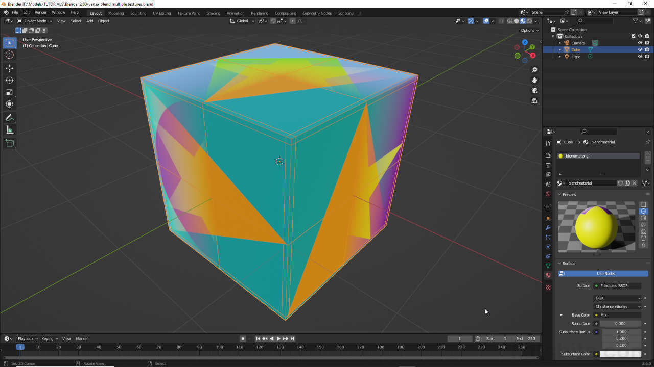
Painting a mesh with different vertex colours to blend a number of materials together.
Blending Normal & Other Maps
In instances where other types of image map are needed e.g., Normal, Specular, etc., they have to be blended as separate sub-trees within the overall material before then being connected through the appropriate input channel of Principled BSDF [17]. As Principled BSDF is an ‘output’ node and cannot readily be mixed with other Principle BSDF nodes, the additional sub-tree has to be created by dropping in a new set of nodes that replicate the initial structure, but for the new maps, or the image and mix node structure of the original setup can be partially duplicated, images then replaced with, for example, normal maps [18]. This process should then be repeated for each image type needed.
Important: when mixing normal maps into a material the Blending Mode of each Mix Color node [i] should be set to Overlay [ii] rather than Mix to ensure the normal maps RGB values are correctly blended with subsequent normal maps (ensure RGB integrity).
Normal maps are a special case for blending as their RGB colouration represent ‘structural data’ that can be corrupted if non-RGB values are introduced. To avoid this, set the Blending Mode [1] filter to Overlay [ii].

Design note: generally speaking, normal maps need to be accompanied by a Normal Map node. Ordinarily while this can be used to increase or reduce the intensity of the normal maps effect, they may also affect the overall material depending on where they are linked into the node tree, before (as A/B input) or after (as Result output) the Mix Color node.

Blending a normal map node-(sub)group [17] through the Normal input of Principled BDF

Blending a normal map node-(sub)group [17] through the Normal input of Principled BDF
