3D Printing & Blender – Scene Setup
Table of Contents
Once the unit of measurement and other scale related settings have been determined, it’s time to set up the rest of Blenders working environment, notably grid scale, camera clip and so on, to make it easier to manage and build meshes for 3D printing.
Grid Settings
Performing some basic tests it was determined that Blenders working Units can be set to millimetres [1] for 1:1 (one to one) correspondence [2] with the slicer being used to prep meshes, and the 3D printer itself.
Design note: settings may differ depending on software and hardware used, for example Creality Slicer is used for prepping meshes (slicer), and for printing, a Creality Sermoon V1 Pro.
This presents a problem insomuch as Blenders default working environment is set to metres; without adjustment all the interface elements that aid construction are about one thousand times too big to be practicable, so need adjusting to compensate for the units being used. First, grid settings.

For 3D printing, Blenders Units system can be set to Millimeters [1], which is then reflected by the dimensions used to describe object size [2] and/or scaling.
To adjust grid display appropriately to fit or match millimetre units of measurement; in Viewport Overlays, change Scale to 0.001 – Scale: 0.001; or for centimetres, 0.01 – Scale: 0.01
Millimeters
– Scale: 0.001Centimeters
– Scale: 0.01
Design note: as a baseline grid scale can be the same as used for the unit of measurement.
When doing this for millimetres the 3D Viewport grid updates so each major subdivision represents 10 mm or 1 cm (green), and 1mm for each minor or smaller subdivision (orange). For centimetres the major subdivision represent 10 cm (green), and 1 cm for minor division (orange). In either case, objects can be snapped, moved or manipulated based on millimetre or centimetre increments even though the main unit of measurement is set millimetres.
Design note: grid Scale and the broader systems unit of measurement, Units, can be set independently of each other.

In Viewport Overlays [3] grid Scale is set to 0.001 [4] to match millimetres as the unit of measurement.

For Centimeter increments set Scale to 0.01 [5].
Object Measurement
To get a better sense of a selection dimensions or size, how big meshes might be in relation to the printer bed, a number of Measurement options are available that display different numerics in the 3D Viewport. To enable, while in Edit Mode, access Viewport Overlays [6]. Here, in the Measurement subsection, click the checkbox corresponding to enable Edge Length [7] – if any selections are active in the 3D Viewport they will display a numeric based on the unit of measurement set in Units, i.e. 2 m [8].
Design note: numerical display is available in Edit Mode only and is selection based, unselected elements remain unaffected. Additional options are available; Edge Angle, Face Area and Face Angle.

In Viewport Overlays [6], enabling Edge Length [7] to display selection metrics while in Edit Mode to help visualise element size and scale [8] – shown above the numerics show each edge as being “2 m”, the ‘unit’ being the default.
Object Volume
While Measurement provides a means to check a selections length (or other numeric), it’s also useful to be able to check an objects overall volume, how much space it occupies. For this Bounds can be used. To enable the option, with object selected, in Object Properties expand the Viewport Display options. Here, click the Bounds checkbox to enable and set Box [9] as the Display Bounds Type shown in the 3D Viewport surrounding the selected object.
Design note: other bounding shapes are available but won’t be as useful for 3D printing.

Similarly, in Object Properties enabled Bounds [9] to display the volume an object occupies to help visualise how much space on the 3D printer bed an object will occupy.
Build Volume
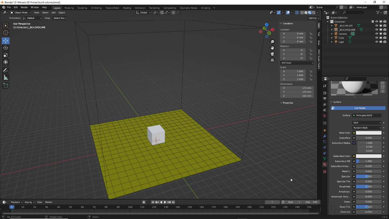
Whilst modelling objects for 3D printing it’s useful to have a build volume reference, a visual aid that’s an ever-present reminder of the 3D printers available build space. A simple way to set this up is to use a cube scaled to the correct size, that’s then displayed as a Bounds object only. To do this, add a cube – Add » Mesh » Cube – to the scene and in the Sidebar – View » Sidebar – set the objects Dimensions to correspond with the 3D printers specifications, e.g. X: 175 mm, Y: 175 mm, Z: 165 mm (175 width x 175 depth x 165 height) [10]. Next, in Object Properties expand Viewport Display options and switch Display As to Bounds [11]. The object will show in the 3D Viewport as a wireframe object.
Design note: as an option the cube can be repositioned so the base sits on the grid, and its origin reset to the same location to reduce the risk of meshes being misalignment as they are processed and 3D printed – doing this essentially resets the ground plain to the grid.
For the build plate, similarly add a Plain – Add » Mesh » Plain – and resize it to fit the 3D printers specifications, e.g. X: 175 mm, Y 175 mm (Z: no necessary). This can then be subdivided, and wireframe displayed, to ‘grid’ the mesh as an additional visual aid for building. Finally for both objects, while still in Object Properties expand the Visibility options and clear the checkmark for Selectable [12], this prevents the object being accidentally selected and moved, in essence ‘locking’ the object(s) in place.

To aid building meshes for 3D printing, use a build volume/build plate proxy – set a cubes Dimensions [10], switch to Bounds [11] and optionally ‘lock’ the items in place by disabling Selectable [12].
