3D Printing & Blender – Dice
Table of Contents
Description
Continuing with the 3D Printing & Blender tutorials, in this exercise we take a look at making a standard six-sided dice for printing using the default scene cube. In Edit Mode the first step is to use Loop Cut and mark a boarder around each face. Next, the pips are formed using Inset and Scale before a Subdivision modifier is assigned to ’round’ everything off. The mesh is then prepped to match the 3D printers environment before being exported as an *.stl file. In the slicer, the dice is set to be printed with minimal infill before export to *.gcode and printing.
Duration: total c. 25 mins (00:25:00).
Info: 1080p.
Suitability: Beginner+.
Source: KatsBits – 3D Printing Dice (c. 20 MB, *.blend, *.stl, *.gcode).
Software/Hardware: Creality Slicer | Creality Sermoon V1 Pro.
Design note: additional considerations to keep in mind when making dice in Blender for 3D printing;
Loop Cut Layout
When defining the initial layout of a dice in Blender, edge roundness and the size and position of the pips, is determined by the ‘frame’ that’s cut into place. In other words, cutting a narrower boarder results in sharper edges and larger pips, whereas the oppose, a broader boarder, results in softer, curved edges with smaller and more densely packed pips. In practice the dice layout may need adjusting to accommodate the 3D printers ability to faithfully represent the design based on the medium used to for printing, i.e. FDM vs resin.
The layout of the initial loop cuts changes the overall appearance or design of the dice…
… so that when subdivision in then applied the appearance/design is further altered by the modifier.Edge Roundedness
Typically a useable or user-friendly placement of pips requires a relatively small frame around each face, but in doing so this often means the edges around the dice are more angular than desired. A simple way to correct for this while maintaining the usability of pip placement, is to scale the outer edges of the dice inwards, essentially collapsing the corners to form simple slopes or pseudo-bevels. When assigned or activated, Subdivision Surface then softens these formations far more readily, all without destroying the underlying structure of the dice mesh.
For uniform scaling ensure all outer edges are selected as Scale (S) then operates based on the groups Median or centre.
Image-left; basic dice with useable pip placement and spacing. Image-middle; outer edges rescaled inwards. Image-right; subdivision modifier assigned showing more rounded edges without affecting pips placement.Edge Bevel
To have more control over outer edge curvature, a more effective approach to dice layout is to use Bevel. This can be manually placed in Edit Mode on selected edges using Bevel (Ctrl + B), the Bevel Tool (toolbar) [1], or using the Bevel modifier [2], assigned in Object Mode. Once bevel has been established, the dice pips can then be laid out as normal.
Some additional contextual notes about using Bevel;
- While all approaches to bevel essentially perform the same function (shortcut, toolbar, modifier), when using the modifier it’s typically necessary to Apply mesh changes before continuing as subsequent loop cut placements can detrimentally affect the resulting curvature.
- 1) When using the shortcut initiated Bevel or the Bevel Tool (toolbar), once the operation has started a ‘value’ can be typed for more precision and uniformity where consistancy might be required across objects, e.g. Ctrl + B » 0.01 will bevel proportionately by the amount set. For the Bevel modifier, the degree of change is set within the control panel with Amount.
- 2) To avoid the Bevel modifier inadvertently affecting everything it can be set to bevel based on Angle, Vertex Group or Weight (Weight Paint). This only then affects what it is limited to, allowing the remainder of the dice to be shaped.
- 3) Independent of a Subdivision Surface assignment, to round a manually placed bevel, while the operation is active (shortcut or toolbar initiated) scroll the middle-mouse button up or down to increase or decrease the divisions, thus ‘smoothing’ the curvature of the effect. For the bevel modifier increase or decrease the Segments value.
When using the Bevel modifier ensure it is applied before further editing the mesh as subsequent alteration will influence what the operation does to the mesh.
Bevelling edges is a more controlled way of smoothing or rounding off the edges as subdivision doesn’t tend to then ‘bleed’ into surrounding surfaces that might then distort certain aspects of the dice. This can be done manually [1] or automatically using the Bevel modifier [2].Fill vs Solid (Voids)
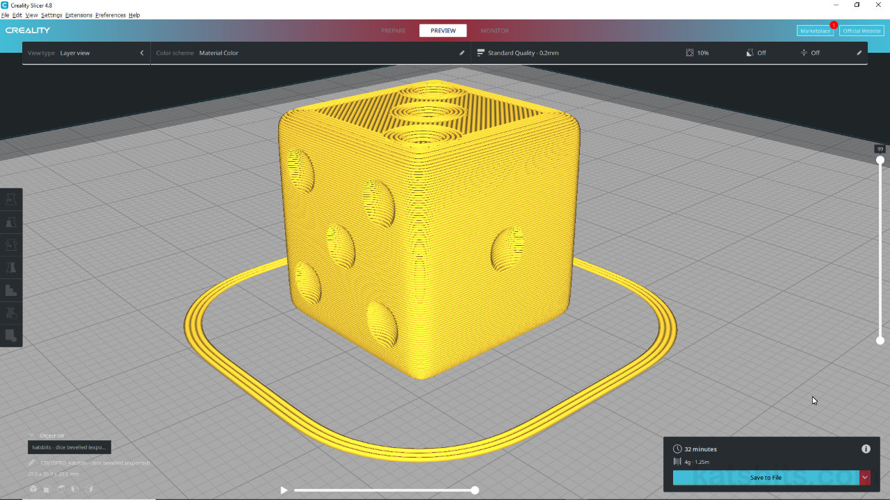
As a general rule-of-thumb it’s not strictly necessary to print solid dice unless there were critical concerns about weight distribution and balance bias affecting throw (where printed dice are to be used). With this in mind, while prepping the dice in a 3D printing slicer, where available set any Infill [3] property appropriately – for all intents and purposes dice printed using a 10% Infill lightens the dice, uses less media, and may not noticeably affect throw, or introduce any lopsided bias that might cause the same number to appear.
Some additional points about Infill or ‘hollow’ dice;
- 1) Infill assumes a solid object is supposed to be printed so reducing the amount forces the slicer to essentially create a void and then partially fill it in a way that supports a structural network to facilitate a complete build.
- 2) Where an Infill option is not available the dice will need to be constructed in Blender to compensate by essentially creating an inside, or empty, void that’s a discreet surface but gives the impression of wall thickness.
- 3) Where an internal void has been created it’s important to enable Backface Culling in Material Properties to ensure surface normals are properly orientated depending on whether they are exterior or interior surfaces – normals point outwards for outer surfaces, and inwards for inner surfaces, with Backface Culling enabled meshes are effectively single-sided.
- 4) When creating wall thickness, either; create a plain mesh that fits inside or, duplicate the outer shell and scale down to fit inside. When doing the latter however, ensure scaling is carried out along normals (Alt + S) otherwise the pips misalign internally, potentially (over) complicating the 3D printing process.
Dice can be designed to have ‘thickness’, that is be hollow on the inside by creating an inner surface (outer shell partially hidden to expose inner facing section).
Even though the inside of a dice isn’t seen, so would generally be featureless, depending on wall thickness, inner surfaces may essentially mirror the outer shell but to the inside.
Solid dice are not strictly necessary so if ‘Infill’ [3] is available – where dice can be printed semi-hollow – use the option.Pip Arrangement
As a general rule-of-thumb dice pips are arranged in opposition; 1 and 6 are opposites, 2 and 5, then 3 and 4. The placement in relation to each other as pairs in opposition varies but is typically laid out as follows (looking at ‘1’ using a ‘right-handed’ layout, – ‘left-handed’ swaps 2 and 5);
– 1 = front
– 2 = left
– 3 = top
– 4 = bottom
– 5 = right
– 6 = backSimilarly, the rotation of ‘2’, ‘3’ and ‘6’ can vary; ‘6’ can be arranged vertically or horizontally relative to other pips; ‘2’ and ‘3’ aligned along a top-left or top-right diagonal.
Printed Dice
As mentioned above, the accuracy and/or fidelity of the actual 3D printed dice will differ depending on the 3D printer used, e.g. Creality Sermoon V1 Pro, the print settings, and the medium. As a general rule of thumb resin tends to be more accurate than FDM of other ‘melt’ mediums, but being more fragile, is prone to damaged. The dice shown below are 20 x 20 x 20 millimetres, took roughly 35 minutes to print with a 10% infill, and used approximately 1.5 metres of media.
3D printed dice on build plate after printing (default design + subdivision), note the fine lines that form as a result of printing using FDM.
3D printed dice with more rounded edges (‘rescaled’ edges + subdivision).


Timestamps
Times are approximate;
– 00:00 : Overview & Initial Layout
– 03:30 : Pips Layout
– 11:00 : Subdivision
– 14:00 : Units & Scene Setup
– 17:00 : Slicer, Prep & Export
