Double-Sided Materials
Table of Contents
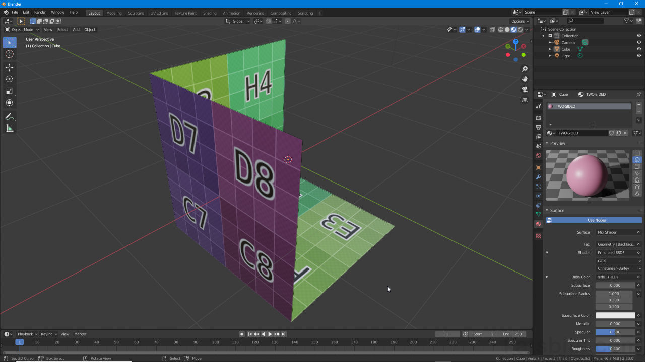
By default Blender 2.8+ renders meshes double-sided (two-sided) by duplicating surfaces to create an ‘inside’ and ‘outside’. The disadvantage in doing this is that both sides are identical; the same UV mapped image appears on both front and back sides. The workaround for this would typically require another object being created with its own set of properties to fulfill whichever side needed to be different i.e. object 1 – leather on one side, object 2 – sheepskin on the other. Using Nodes however, it’s possible to avoid needing to do this using a double-sided material (two-sided).
Download: KatsBits – Double-Sided Materials | c. 700 KB (*.blend).
Double-sided Meshes
As briefly mentioned above Blender 2.8+ renders surfaces double-sided by default. It typically does this by duplicating the (often) outward facing surfaces of an object and flipping or inverting them inwards (or vice versa). Aside from their orientation this means both sides are identical, they use the same base materials, the same properties, the same UV mapping etc., with changes to any one aspect being immediately and simultaneously shown on both sides.
Design note: although the ‘viewport’ double-sided effect is ‘on’ by default it can be disabled a number of ways depending on which Viewport Shading mode is active. For more on this see Backface Culling.
Ordinarily to work around this problem objects would need to be hard or physically duplicated and set up to use their own unique properties, materials and UV’s before being inverted (Mesh » Normals » Flip) to produce a model comprising two meshes, one with surfaces pointing outwards, the other with surfaces pointing inwards.
Design note: game assets may still require use of two meshes, one being inverted.

Ordinarily double-sided meshes can be created using two separate objects with independent properties and materials assignments facing away from each other, typically this might be done for models used in games where inside and outside surfaces need to differ.
Double-Sided, Different Material
To set up a basic double-sided material, first from Material Properties create and assign a standard Material. Next, in Shading Workspace add an Image Texture node and associated image (Add » Texture » Image Texture) – the image will appear on both sides of the mesh.
Design note: images assigned to the Image Texture node (and material overall) can be internally Generated, UV Grid etc., or externally loaded, *.tif, *.gif etc., as normally expected when setting up a material.

A basic material is first assigned to the object so the same image appears on both sides (subject to the object being UV unwrapped and mapped and scene set to Material Preview mode).
To this basic material add another Image Texture node (Add » Texture » Image Texture), a Principled BSDF node (Add » Shader » Principled BSDF) and a Mix Shader (Add » Shader » Mix Shader). Create or assign a different image to this second Image Texture node and connect its Color output to the Base Color input of the second Principled BSDF node. From here link the BSDF outputs [1] of both Principled BSDF nodes to each Shader input of the Mix Shader [2], then the Shader output of the Mix Shader to the Surface input of Material Output [3]. This blends the two separate images together, displaying them as such on the both sides of the mesh.
Design note: assignment can be inverted by switching the Shader inputs of the Mix Shader.

Once the basic material is set up another Image Texture and Principle BSDF nodes are added alongside a Mix Shader which are linked together – Image Texture to Principled BSDF, the two Principle BSDF nodes [1] to Mix Shader [2], finally Mix Shader to Material Output [3].
Finally to this combination add a Geometry node [4] (Add » Input » Geometry) and link its Backfacing output to the Fac input of the Mix Shader [5]. This filters the blending separating the two textures so they display on the mesh correctly, one for each side (obverse and inverse).
Design note: although a double-sided material shows a different image on either side of a surface it still ‘mirrors’ position, images are mapped to an object or surfaces using the same UV’s – selecting or modifying one image via UV placement applies to both, they are not distinct (cf. below for more).

Once the nodes are linked up a Geometry node [4] is added and connected to the Fac input [5] of the Mix Shader, which then correctly displays the two images, one on either side of the mesh.

Node tree for a basic two-sided (double-sided) material that displays a different image on either side of a surface.
Double-Sided, Different UV’s
Whilst the basic two-sided material described above displays different images on either side of a mesh or surface, they are mirrored because they use the same UV map or mapping coordinates. For the material to accommodate different image positioning, both the object and material need to be altered slightly. First the Object.
Design note: because objects assigned double-sided materials are still physically single sided, texture placement, what area of each respective image is used, is determined by the same UV. In other words although a given UV might be selected the image section associated with it will be the same for both sides of the mesh/materials regardless.
To set up a mesh so a single double-sided material displays mapped images differently, two UV maps are needed. To do this, with the mesh selected access Object Data Properties and in the UV Maps subsection click the [+] button to the right of the aperture, creating another second instance (double-click and rename as required) – two instances are needed so repeat if this is not the case [6 & 7]. Switch to UV Editing Workspace and select each UV Map entry in turn (from Object Data Properties) – each layout will then toggle in the UV Editor (and be editable) when the respective map entry is selected in UV Maps – and edit as necessary.
Design note: although there are no limits to the number of UV Maps an object can have, double-sided materials can only use two from a selection, one for each side of a surface.


To accommodate textures being mapped differently on either side of a mesh when the double-sided material is assigned, the mesh needs two UV Maps [6 & 7] (rename for clarity where appropriate).
To then set up the material so each UV map is associated with a specific (UV mapped) image; switch to Shading Workspace and add a UV Map node [8] (Add » Input » UV Map). Once placed click the UV Coordinate to used for mapping input box/drop down, select an entry from the list to make the association and then link UV output of the UV Map node to the Vector input [9] of the Image Texture node. The associated image will then appear on the appropriate side of the mesh. Repeat for the other image block; add a UV Map node, select the UV map to use and then link to the Image Texture node, UV output to Vector input. The end result will be a different texture on each respective side of the mesh with independently editable UV’s.
Design note: depending on Shader input order to the Mix Shader images may appear inverted relative to the physical mapping of the UV’s. This can be corrected physically inverting the UV’s in the UV Editor or adding a ‘swizzle’ to the material tree that flips the UV on the appropriate axis. To do this, in Shading Workspace add a Mapping node [10] (Add » Input » Mapping) then links as follows; UV output (UV Map) to Vector input (Mapping), Vector output (Mapping) to Vector input [11] (Image Texture). Use the various options of the Mapping node to then correct for Rotation, Location and/or Scale.
To correct image flipping from within the material use a Mapping node [10] as this then provides a number of options to ‘swizzle’ the result, to numerically change rotation, location, scale characteristics of the (node chain) linked image (typically applied to both although only one shown above).


To accommodate each side of the mesh/material using a different UV Map a UV Map node [8] has to be associated with each Image Texture block, linked to Vector input [9], ensuring one map, one image.
