Minecraft Legends Style Character in Blender
Table of Contents
Description
In this exercise we make a Minecraft Legends style character, a player with a ‘toon’ like black outline. We first make the basic character from a series of cube Primitive blocks that are UV unwrapped and mapped to a standard Minecraft Skin. Next its rigged. Initially this is by setting up a basic skeleton with bones set to articulate each part of the body, arms, legs, torso and head. To make the rig more flexible a number of additional bones are included, some then associated with Inverse Kinematic (IK) assignments that change the skeletons behaviour. With body parts linked to the skeleton the outline can be created using Duplicate and assigning their own ‘outline’ material. Once all the mesh parts are done the character is then animated using the Action Editor and standard bone posing and keyframe marking their positions to the editors timeline.
Download: Katsbits – Minecraft Legends (c. 500 KB | *.blend, *.png).
Design note: the flexibility afforded by use of Inverse Kinematics depends on the complexity of the skeleton. While simple IK are relatively straightforward to use regardless as they perform a basic ‘inversion’ function, more complex IK require a certain degree of redundancy simple IK may not need (cf. “Rigging – IK’s” below). It’s important then to bear in mind that a given skeleton may need to be adjusted or modified after-the-fact.
Unit Scale
Setting the projects Unit Scale [1] to 4.000000 (default 1.00000) does not alter the Cube, it changes the scene/grid. This is done because the dimensions used by Minecraft are relative to ‘power-of-two‘ (multiples of 2), which makes a properly proportioned character much larger if it were built using Blenders inherent Unit. If the mesh were then to be used in a larger project, a rendered animation for example, adjustments would need to be made to cameras and lights to compensate for this scale difference.
Increasing Unit Scale [1] to make it easier to shape the characters body parts by keeping measurements relative to Minecraft.Body-Part Dimensions
The dimension of each body part is scaled relative to the number of pixels available in the 64 x 32 pixel image UV mapped to the character (for more information on this see “[Minecraft] how tall is the Minecraft player in Blender“);
• Head = 8 x 8 x 8
• Torso = 8 x 4 x 12
• Arms = 4 x 4 x 12
• Legs = 4 x 4 x 12
The full dimensions for each body part.Joined Mesh
The characters body parts can be left separated, ostensibly for ease of rigging and set up, or joined together to form a single unified mesh object, e.g. selecting an ‘arm’ selects the entire object. This is optional and can be done at any point once the body parts are available. Joining is also not specifically necessary to make a functional character, all it does is reduce the number of objects being worked on/with [3]. To do this, Shift-click each body-part and from the Object menu click Join [2] – Object » Join (Ctrl + J). When joining objects, the Origin of active object, the item highlighted brighter orange, becomes the new objects origin so may require adjustment.
Use Join [2] to attach all the objects into a single mesh [3]. This is optional and can be done at any point once the parts are available.Rigging – Root
By default Blender places Armature objects in a upright position so the single bone they include aligns with the Z axis [4] (up/down). This can be changed, for example by rotating the bone to lie on its ‘back’, which then aligns it to the Y axis [5] (pointing backwards from the character when looking at it in ‘Front’ view). To do this, in Edit Mode select the individual bone to be changed and rotate it appropriately using the Rotate widget and the corresponding coloured ‘axis’ handle, or pressing R, then any one of X, Y, or Z to lock to a specific axis, e.g. R » X » -90 (type the value).
Root will be aligned to the Z axis by default [4] but can be rotated [5]. This may need to be done if the character is to be used in a third-party environment.Rigging – IK’s
The general purpose of Inverse Kinematics (Kin-eh-mat-ic) is to change the behaviour of a bone chain independently of any particular bone within the chain, typically to the inverse or reverse of the chains natural function, essentially the order in which bones are created. For example, a chain comprising a hip, thigh, calf and foot bone articulates relative to the hip bone, when that moves, all other bones down the chain also move relative to it.
This inherent hierarchical behaviour also means bones within the overall chain have to be moved individually or as part of a sub-chain; moving the thigh also moves the calf and foot (thigh » calf » foot); moving calf also moves foot (calf » foot); foot moves on it’s own (foot). This is a top-down parent » child hierarchy [6].
For simple Inverse Kinematics, when set up so the foot bone controls other bones up the chain, Chain Length can be altered in the modifiers settings to adjust the number of bones included in the chain; when foot then moves it controls the entire chain depending on the number of bones included. This is an inverse (inverted) bottom-up child » parent hierarchy [7].
For more complex articulation bone relationships can be changed based on the bones referenced by the modifier, changing a simple Inverse Kinematic into a more complex IK Constraint or IK Solver [8].
Additional note: the use of more complex IK Constraints and IK Solvers typically obligates a degree of redundancy, the addition of bones that might not otherwise be needed for simpler or more direct skeletal control.
An Armature [6] by default has a top-down articulation hierarchy. Adding a simple Inverse Kinematic [7] changes this to bottom-up. Setting IK Constraint [8] can further mix and match behaviour.Toon Outline & UVs
Because the toon outline is created using duplicates of the main body it also then uses the same UV mapping, i.e. the UV layout conforms to the Minecraft ‘skin’ image each body part is UV mapped to. For simplicities sake, as the outline is a single uniform colour, the copied mapping can be left untouched. However, if the blocks from which the outline is constructed are created by adding new objects to the scene, each can be UV mapped to use a rough or simple layout (assuming single colour outline), for example using Reset to unwrapped each face 1:1 – UV » Reset or UV » Unwrap » Reset (U » [option]).
Additional note: assuming an image is mapped to the outline it doesn’t need to be any larger than the original ‘skin’ texture, i.e. 64 x 32 pixels. As it does not include any discernible ‘feature’ detail it can be smaller, e.g. 1 x 1 pixels.
Copied body part also include the original objects UVs. Where these don’t exist, from dropping in new mesh objects, a simple UV Reset will suffice for the ‘toon’ effect.Auto Keyframing
To make the animation process easier Auto Keying can be enabled to automatically insert appropriate keyframes into the Action Editor timeline whenever a bone is moved and/or posed. This option is not available to the Dope Sheet or Action Editor so has to be enabled from the default Timeline Editor. To do this, in the default Layout workspace click the Auto Keying button [9] in the Timeline Header, then in Keying, select the Active Keying Set [10], the type of data that’s to be captured, this typically wants to be Location & Rotation or Location, Rotation & Scale, and ensure the New Keyframe Type is set to Keyframe [11]. This will then capture a given bones location, rotation and scaling as a keyframe in the timeline.
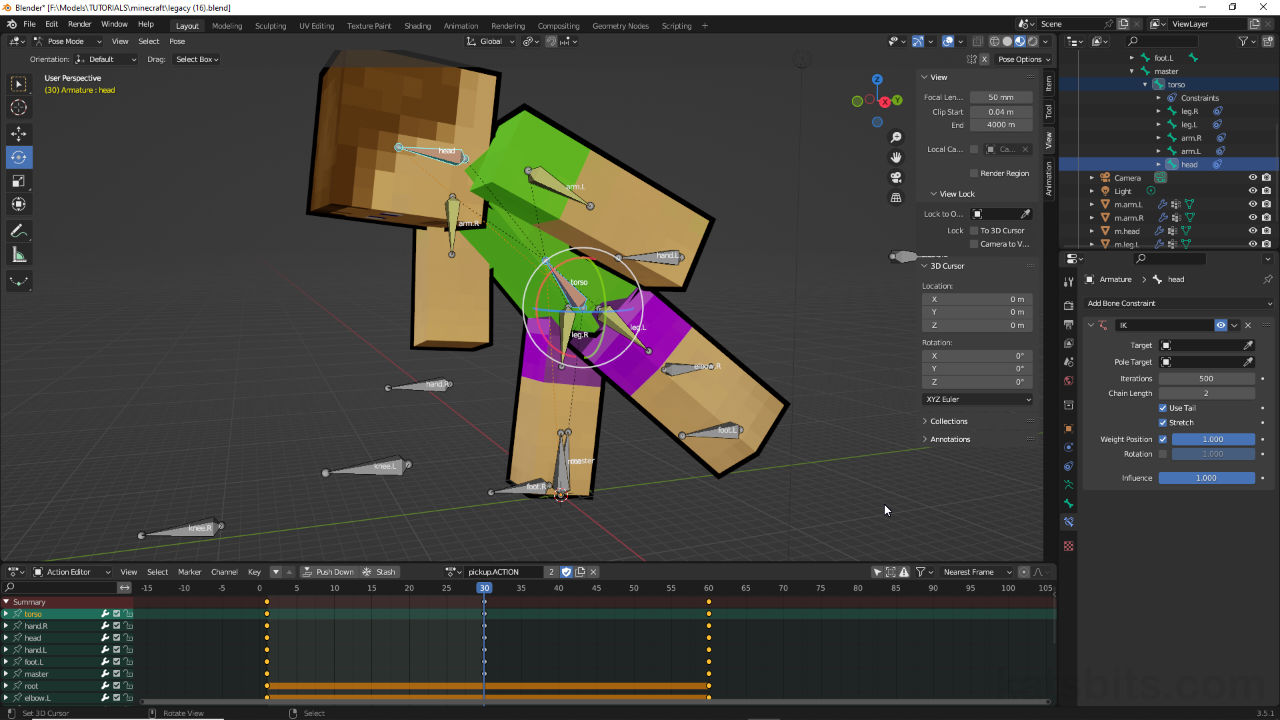
Setting the Auto Keying function [9] to capture a bones Location, Rotation & Scale [10] as a Keyframe [11] in the Action Editor timeline.Post-Rig Bone Additions
Adding bones to the rig after the fact is relatively straightforward (select Armature, switch to Edit Mode then Add » Single Bone, use Extrude, or Duplicate an existing bone) but may affect the skeleton and any Inverse Kinematics differently depending on where they are placed. Changing how the IK resolves therefore, may be a necessity. Adding extra bones may also change any existing keyframe and/or bone pose data depending again on where the supplementary bones are placed – attaching a bone to ‘root‘ [12] for example may not adversely affect the skeleton as much as dropping one in between ‘hand‘ and ‘arm‘ [13].
Additional note: depending on how and where extra bones are placed they may need to be Connected to or disconnected from bones above them in the chain (Parent bones). This can be done by selecting the new bone [i], and in Bone Properties, enabling or disabling the Connected checkbox [ii].
Enabling or disabling the Connected checkbox in Bone Properties will physically attach bones together so they move as a section – bones above and immediately below will move when another is manipulated.
Adding a bone to ‘root’ [12] may affect the skeleton differently than adding one between ‘arm’ and ‘hand’ [13].


Timestamps
Times are approximate;
– 00:00:00 : Overview & Body Parts
– 00:05:00 : Material & UVs Unwrapping
– 00:29:00 : Rigging Basic Skeleton
– 00:37:00 : Bone Rotation
– 00:54:00 : Rigging IK Constraints
– 01:05:00 : Bone Constraints
– 01:22:00 : Toon Outline
– 01:42:00 : Animation
