Emboss, Engrave Text in Curved & Non-linear Surfaces
Table of Contents
Embedding, engraving or embossing text into a flat surface using Boolean is relative straightforward. Curves and non uniform shapes however, present an entirely different challenge. There are two ways text can be made to Boolean non-flat surfaces; by manually shaping text to fit approximately (simple), or using a guide to fit more accurately (complex).
Design note: as a general rule-of-thumb it’s preferable to edit non-destructively, that is, modifiers assigned to meshes should remain active rather than being applied so adjustments can be made as needed, negating rebuilds to change something. Using Boolean to engrave or emboss text into surfaces is no different in this regard.
Basic Boolean Setup
For Boolean to work properly at least two objects are needed; a target and an operator. The target is the object affected by the Boolean process, the operator the object that does this. The basic set up then is to add a Text object – Add » Text – and in Object Data Properties [1] give it some initial substance, Extrude for example to make the flat text more three-dimensional. Once done, the Text can be converted into a mesh object ready for use – Mesh » Convert » Mesh.
Download: KatsBits – Boolean Text Curves (c. 600KB, *.blend).
Design note: for more on Boolean generally see here, and here for standard Boolean text.

Text object that acts as the Boolean operator with some basic properties assigned [1] before being converted to a mesh – wireframe enabled for clarity.
Once the text is setup, the object to be affected by it needs a Boolean modifier assignment. In Modifier Properties click Add Modifier then Boolean from the available options – Modifier Properties » Add Modifier » Boolean. In the panel that appears the basic properties can be set; the type of operation – Intersect, Union or Difference; the Object to target, e.g. ‘Text.001‘ [2]. These two steps set up the basic parameters needed for the text to Boolean the object when moved into position [3].

The parent mesh of a Boolean operation, a cylinder, showing the the text set as the target Object [2] operator (Text.001 in the above), and the resulting Difference effect [3] this has on the cylinder – wireframe shown for clarity. Text, being flat, only cuts into the mesh where it touches the curvature of the cylinder.
Simple Curves & Boolean
To emboss, engrave, indent or otherwise curve or shape text around an object, before conversion to a mesh the objects Origin [4] may need to be adjusted so text bends or wraps uniformly around this Pivot Point. To realign the text so the Origin sits centre-of-mass, in Object Data Properties with Text object selected, access the options under Paragraph [5] (click heading to expand if not visible) and adjust the Horizontal and Vertical settings under Alignment [6], e.g. Horizonal: Center, Vertical: Center. The text will realign itself center/center relative to its Origin [7].
Design note: the Origin is the point around which the meshes are manipulated or deform; in this context centre-mass equates to uniform deformation on all axes; off to one side or the other and text will warp based on that point (the object itself may need to be repositioned in Object Mode to compensate for the Origin’s realignment).


Generally speaking the Origin [4 & 7] of the Text object should be adjected to ensure the text curves uniformly. This is optional and depends on the type of deformation needed from the procedure. In Alignment [5] properties change the Horizontal and Vertical values both to ‘Center‘ [6].
Next, to ensure the text deforms reasonably well a Remesh modifier can be assigned to reconstitute the text object so each letter is defined by quadradic faces instead of Planar surfaces as would be done using Decimate. This creates a more formalised internal structure or topology.
Design note: Remesh can be assigned while the text remains a dynamic vector-based object or after conversion to a mesh. The former (dynamic text object) accommodates changes of font, style, resolution and so on without unduly affecting Remesh itself. The latter (mesh object) does not.
If Remesh is assigned to text before conversion to a mesh it can be modified on-the-fly without negatively affecting the retopology that occurs.

With Text object (before conversion) or mesh (after conversion) selected, in Modifier Properties click Add Modifiers and select Remesh [8] from the Generate list – Modifier Properties » Add Modifier » Remesh. In the properties panel that appears click Sharp [9] and disable or deselect the Remove Disconnected [10] checkbox. The text will appear albeit in low, blocky resolution. To change this and increase the clarity of the text increase the Octree Depth value, initially until the entire object is visible or legible, for example Octree Depth: 6.
Important: increases to Octree Depth, like Subdivision Surface, greatly increases the resolution of the mesh, which in turn increases the structure considered for a Boolean operation.

The Remesh [8] modifier will initially seem to ‘destroy’ the object as it tries to reconstitute the underlying structure and rebuild it using quads instead of Planar surfaces as would be used with Decimate.

Increasing Octree Depth essentially subdivides the mesh, bringing back the initially lost detail. Enabling Sharp [9] and disabling Remove Disconnected [10] ensures the effect applies to the entire object.
Once the Text object is set up it can be converted to a mesh as normal. In the Object menu click Convert, then Mesh [11] – Object » Convert » Mesh. In the Convert To [12] overlay bottom-left enable Keep Original to keep and maintain the original Text object [13] (the new mesh is appended .001 to identify it from the original text).

As always for Boolean operations, Text needs to be converted to a Mesh [11] before it can be used. Keep the original text object [12] so its easier to update and re-convert it if need be [13].
With this done the mesh is ready for Boolean. However, when linked to the Boolean modifier as the operator Object, this will perform a standard Intersect, Union or Difference operation and won’t bend to fit the object. To address this two additional steps are needed; assigning a Simple Deform modifier and dropping in an Empty to act as the modifiers orientation target.
Design note: depending on the type of deformation required other Deform modifiers can be used with differing results, Warp, Mesh Deform etc.
With this in mind, from Modifier Properties add a Simple Deform modifier from the Deform column – Modifier Properties » Add Modifier » Simple Deform [14]. The mesh may twist (default behaviour) or change shape slightly confirming assignment.

To bend the text mesh around something a Simple Deform [14] modifier needs to be assigned which twists the mesh by default in confirmation.
Next add the Empty. From the Add menu select Empty, then any one of the available options, e.g. Arrows – Add » Empty » Arrows. This places the object at the cursors location. For this technique to work relative to the text mesh and it wrapping around the cylinder in the Scene, the Empty needs to be located relative to the text’s Origin. This can be done using Snap. To do this first select the Empty then shift-click the Text creating a selection group. From the Object menu select Snap then Selection to Active – Object » Snap » Selection to Active [15]. The Empty immediately jumps to the Origin of the text object [16].
Design note: as the text object’s Origin was set to center/center prior to conversion this is where the Empty will snap, however, it can be manually moved or located anywhere using the manipulation widgets or numerically changing the Location, Rotation coordinates available in Object Properties or the Sidebar. Additionally, as the Empty is an orientation target or reference for the modifier, the type or specific form this takes has no bearing on the end result.
Now the orientation target is in place select the text mesh and in the Simple Deform modifier [17] set the Empty as the Origin target object using the eyedropper and selecting the Empty in the 3D Viewport, or selecting it from the Offset the origin and orientation of the deformation list (square icon with outline). As the text is to wrap around the cylinder (in this example) set the type of operation clicking the Bend button and setting the Axis to Z. This will wrap the text around the vertical pole defined by the Empty and based on the Angle set. Change this to alter how well the text deforms to match and wrap the object while continuing the Boolean operation.
Design note: if the Remesh modifier is assigned to the text object after conversion it can be changed [i], altering the degree to which structure is cut and formed based on the Octree Depth set while the effect is live and still being shaped by the Simple Deform modifier [ii].
If Remesh is assigned after the text object is converted [i], mesh structure can be changed on-the-fly while Boolean and Simple Deform are live [ii].


Using Snap [15] the Empty can be positioned at the text objects Origin [16]…

… which then accommodates the properties needed to deform the mesh to match the cylinder [17].

With everything set up correctly the Boolean operation will remain active and behave based on the operation set for that modifier – text mesh displayed as Bounding Box for clarity.
Complex Curves & Boolean
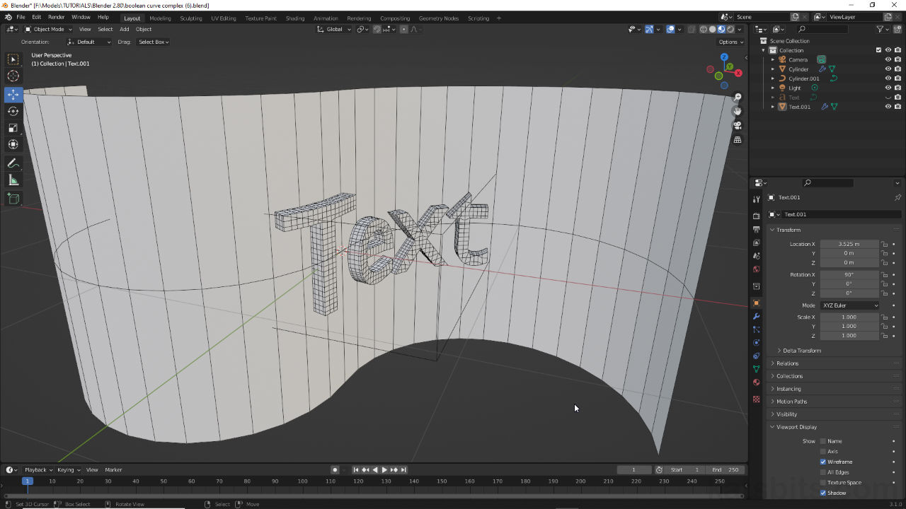
Using Boolean to indent, emboss or engrave text on more complex shapes requires a slightly different approach as the text operator needs to be guided more formally so it matches the shape rather than it being deformed to fit. The initial prep is basically the same so the target and operate objects should be set up as normal for a Boolean operation; text converted to a mesh [18]; Boolean modifier assigned to object that targets the operator (text), which ultimate has the text clipping or adding to the surfaces being acted upon [19].

Initial Boolean setup is the same as for other types of operation; text object converted to a mesh and cleaned up using Decimate or Remesh [18]…

… which then operates on the mesh to emboss or engrave text into surfaces [19] – text displayed as Bounds for clarity – Object Properties » Display As » Bounds.
Once the basic Boolean operation is set up, the next step is to define the path along which the text deforms and assign the modifier that facilitates that. As this needs to be relatively accurate the simplest way to do this is to select an edge loop within the mesh, detach it as a separate object and then convert that to a vector-based path. With that done the Curve modifier can be assigned to the text and targeted at the path.
Design note: for sake of accuracy the path is converted from a segment of the mesh but can be a manually placed curve that’s edited into shape – Add » Curve » [option].
First then, is to set up the path. With target object selected, that is the mesh affected by the text, in Edit Mode select an edge loop that’s to be used as the path [20] and from the Mesh menu copy it using Duplicate [21] – Mesh » Duplicate (or Shift + D). Press Esc to reset the new loop and whilst still selected use Separate [22] to detach it as an independent object – Mesh » Separate » Selection (or P » Selection). Exit Edit Mode and select the new edge loop object.

With an edge loop selected in Edit Mode [20] it can be duplicated [21] (shown in Wireframe for clarity)…

… and detached as an independent object using Separate [22] ready for conversion (shown in Wireframe for clarity).
The object may not be immediately visible or selectable because the previously assigned Boolean modifier has also been duplicated. This needs to be removed. In the Outliner highlight the corresponding entry and in Modifier Properties remove the Boolean clicking the X [23]. The object should then appear, which can now be converted to a path. To do this, from the Object menu select Convert then Curve [24] – Object » Convert » Curve. The object will now be a Poly based path.
Design note: after converting nothing will appear to have changed because line-art and edge loops are almost identical in appearance. To confirm toggle into Edit Mode [iii] and check whether edge loop vertices are instead node points [iv].
Confirming conversion of the edge loop in Edit Mode [iii], check to see if vertices are now node points [iv] (other scene objects hidden for clarity).


Once the edge loop is separated and the Boolean modifier removed [23] it can be converted to a Curve [24] ready for use (other scene objects hidden for clarity).
Before linking to the path object, the mesh needs to be positioned so the two Origins match. To do this, select the mesh then shift-click the path. From the Object menu select Snap then Selection to Active [25] – Object » Snap » Selection to Active (or Shift + S » Selection to Active (3)). The text mesh will snap to the same location as the path based on the two objects Origin points [26].
Important: the physical relationship between path and object is determined by the relationships between Origins. If both are in the same place the text mesh generally deforms along the path itself. If displaced the text still follows the path but may be some distance from the object its operating on. This behaviour can be changed altering the position of the text mesh in Object Mode, or moving the mesh in Edit Mode, relative to the path.

For Boolean the text mesh should be positioned to travel along the path, which is done by snapping [25] the two objects together so their respective Origin points [26] are in the same location (curved mesh hidden for clarity).
With this done, to link the text mesh to the path a Curve modifier is used. To do this, with text selected, in Modifier Properties assigned a Curve modifier from the Deform column [27] – Modifier Properties » Add Modifier » Curve. In the panel that appears set the Curve Object [28] to the path just created; use the eyedropper to select the path in the 3D Viewport or select it from the Curve object to deform with list (white square icon). Immediately upon doing this the text object will warp and deform to fit the path where it can also be repositioned relatively using the manipulation widgets Move, Rotate and Scale.
Design note: once linked to the path, if the text appears backwards this can be fixed in one of two ways by changing the direction of the path or changing the rotation of the text. To change the path, select the curve and toggle into Edit Mode. Here select all the path nodes [v] – Select » All (A), then in the Segments menu click Switch Direction [vi] – Segments » Switch Direction. The text will flip the correct way around (may need to be repositioned along the path).
If the text appears backwards it can be reverted the correct way round by flipping the direction of the curve in Edit Mode using Switch Direction.To change the text mesh, with it selected, in the Sidebar [vii] or Object Properties [viii], change the Z value for Rotation to 180, i.e. Rotation Z : 180. The mesh will flip around the Z axis to face the right way (changing the orientation of the text itself can be done on multiple axes whereas the path can only be reversed).
The text itself can be inverted from the Sidebar or Object Properties, simply change the Rotation value appropriately, i.e. 180.


Important: depending on the type of path described certain types of Boolean operation may have issues crossing what is in effect a positive or negative coordinate threshold, i.e. 1.000 vs -1.000 or face normals being concave versus convex. In these situations Boolean sections may disappear or render incorrectly relative to what may be wanted, the effect embossing or engraving entirely in a surface. The issue can be resolved to a degree changing the Solver for the Boolean operation from Exact (default) to Fast.
The complex nature of surfaces that curve in more than one direction can cause issues for certain Boolean operations, which result in incomplete or broken renders.


With path now available and objects positioned where they need to be a Curve modifier [27] can be assigned to the text mesh…

… which is then targeted, via the Curve Object setting [28], at the path, which the text now conforms to and follows.

Text mesh and background merged using a Boolean operation (Union), text following a path and deforming dynamically to fit as its moved and manipulated.
Compound Curves (Multiple Axis)
Generally speaking text embossed or engraved around or across curved surfaces using Boolean more often than not run in one direction or along a single axial plain however that might be shaped – an extruded ‘S’ shape for example. For surfaces that curve on multiple axis this setup needs to be adjusted through the inclusion of additional modifiers catering to specific axes.
Design note: due to the way meshes deform when traversing a curve it may lead to issues when other axes need to be considered even though the set-up may be correct.

Embossing or engraving text is usually done along one axis (image-left) making it easier to setup. On the other hand multiple axes (image-right) need a slightly different approach.
To accommodate multiple axes manually, set up the initial deformation as described for Simple Curves above, that is, text mesh positioned where it intersects the target object, Boolean assigned to object being modified and text assigned a Simple Deform [29] modifier (optionally Solidify and/or Remesh depending on how the text is given thickness and definition) that’s targeted at an Empty used to define the modifiers deformation orientation. This will Boolean the the two meshes around one axis, which in-turn may result in a partial effect if text doesn’t intersect too deeply [30].

To accommodate multiple axes set the target and operator up as for a single axis curve with Simple Deform [29] modifier assigned to the text that’s to be bent to shape.

Bent around a single axis Boolean doesn’t properly penetrate the mesh top and bottom [30] (text hidden for clarity).
To address this, with text mesh selected add a second Simple Deform modifier [31] and make sure it sits below the first instance, then changes the settings to match so; Bend as the type, Origin to use the same Empty as the first modifier instance, and Axis to X (or another axis other than the one initially used in the first modifier instance). Finally change Angle to bend the mesh so top and bottom [32] now clip.

Adding a second instance of the Simple Deform modifier [31] to cater to a second axis around which text should bend, resulting in top and bottom [32] of text properly clipping (text hidden for clarity).
If the surface affected curves on all three cardinal axes, X, Y and Z, then another final instance of Simple Deform can be added to accommodate the axis not previously covered. With text mesh selected, again add a Simple Deform modifier [33] to the stack and change its settings to reflect the other instances [34]; Bend set as the type, Origin set to the same Empty and Axis set to Y. Finally change the Angle value to account for any bending or twisting that might be needed for the text to properly, positionally and proportionally intersect the mesh.
Design note: when using separate Simple Deform instances to accommodate each axis, their order in the stack may also influence the effect, for example Z being above X and Y may cause a slight taper to the text, something that might be addressed switching the order so Z sits at the bottom. This can be done by click-dragging the panel handle [ix] upper-right corner of each panel and re-ordering them in the stack.
The order modifiers appear in the stack can have a positive or negative affect on the effects applied to projects. They can however be reorganised click-dragging the panel handle [ix] to move panel up or down the stack.


Adding a third instance of Simple Deform [33] then accommodate all three cardinal axes and straightens out the text [34].
Where a path [35] has been used to define the general behaviour of the text mesh, Simple Deform instances can be included to accommodate axes not influenced by the Curve modifier [36]. For this, once the Curve path has been established, add a Simple Deform [37] modifier and set it up similarly as described above; Bend as the type, Origin set to an Empty target in the scene as described above, with Axis set appropriately. Finally change Angle to adjust the text to suit [38].
Important: the underlying set up that defines how a text mesh conforms to a path differs sufficiently from using other deform modifiers that their behaviour may be affected as a result. This might mean Simple Deform not behaving quite the same way despite being set up as it ordinarily would be.

When following a path [35] text will only do that, follow the path, it doesn’t deform or shape itself [36] in any other way so gaps can appear…

… the solution is to add a Simple Deform [37] modifier to adjust the mesh along specific axes to compensate [38].
Subdivision Surfaces
In most instances the use, or presence, of a Subdivision Surface modifier in the modifier stack won’t adversely affect indenting, engraving etc. text into surfaces using Boolean so long as modifier stack order is correct; Subdivision Surface must sit before (above) Boolean. If not the Boolean operation becomes the basis upon which Subdivision acts, which distorts the result. This should be the reverse; Boolean should always act upon a subdivided surface, never the other way around.
Design note: Subdivision Surface may cause meshes to clip or occlude Boolean text. To compensate edit the mesh carrying the Subdivision Surface modifier and/or repositioned or adjust the texts curvature to compensate.
If a Boolean operation has already been performed but has not been ‘made real’ (Apply), add a Subdivision Surface Modifier – Modifiers » Add Modifier » Subdivision Surface. It should initially appear at the bottom of the stack below other modifiers. Click-drag the manipulation handle top-right [39] and position the panel above the Boolean instance [40]. This reorganises the stack and instantly corrects the active operations.

Adding more modifiers to the stack places them at the bottom below others. To re-order modifier click-drag the panel manipulation handle top-right [39]…

… and drag the panel above any Boolean modifiers that might be present in the stack [40]. This corrects the operation order and fixes the operation.
