Engrave, Emboss, Indent Text in Flat Surfaces
Table of Contents
Boolean is a useful way to subtract, indent or engrave material from another object, add, emboss or combine objects together to form new shapes. It works extremely well on uniform, regular or flat surfaces, planes or primitives but has significant issues with complex shapes, text in particular. With this in mind there are a number of things that can be done to mitigate or alleviate such issues.
Basic Boolean Text
The basic procedure to engrave, indent or emboss text into something using Boolean is to add a Text object to the scene, format and then convert it for use. A Boolean Modifier is then assigned to the object that’s to be affected by the text, and the type of interaction between objects enabled – subtractive, additive or combined – for the desired result.
Download: KatsBits – Boolean Text (800 KB | *.blend).
Design note: the Boolean modifier is assigned to the object being cut or modified not the object doing the cutting.
To add the text, from the Add menu select Text – Add » Text (or Shift + A » T) [1]. The word “Text” will appear at the 3D Cursors location in the scene. This is the initial text object that can be edited and modified. To do that, with text object selected access Object Data Properties [2] (the green ‘a’ icon). Here various options are available [3] to change different aspects of the text including (but not limited to) the font type and style, whether it has depth, its resolution and so on.

Dropping a text object into the scene from Add » Text [1]…

… which can then be modified in Object Data Properties using the various options available to change its appearance; font type, size, thickness and so on [3].
For basic Boolean to work correctly text needs to have some degree of depth so individual letters can penetrate through surfaces, it’s this interaction Blender uses to determine the behaviour of the operation and the end result, additive, subtractive or merged meshes. In Object Data Properties this can be done altering the Extrude [4] value in the Geometry [5] subsection (click the heading/label to expand the options if not visible). Increase the number sufficient for the text to penetrate through any surface it should affect, e.g. Extrude 0.25 m.
Design note: Text objects, vector or line art generally, can be given depth by alternatively assigning a Solidify modifier. To do this, select the Text object then in Modifier Properties click Add Modifier then select Solidify from the list – Modifier Properties » Add Modifier » Solidify. In the panel that appears change Thickness [i] to alter the object; + or positive values extrude down, – or negative values extrude up (assuming text appears flat on the grid). WARNING: using the Solidify modifier may negatively impact other aspects of the process.
The Solidify modifier can be used as an alternative to editing the Text objects properties [i] but may unduly or negatively affect other aspects of the Boolean procedure.


The most basic change needed is for the text to be given some depth. This can be done increasing the Extrude [4] value in the Geometry subsection [5] – values need to be large enough for resulting text to interacts with all surfaces it should affect.
With basic properties of the text object established it finally needs to be converted into an editable mesh, the same object-type the text is to interact with. To do this, with Text object selected, from the Object menu select Curve then Mesh – Object » Curve » Mesh [6]. The Convert To overlay will appear bottom-left. Here make sure Target is set to Mesh [7], and if a copy if the Text should be produced enable Keep Original to maintain the Text object itself. A duplicate object will be added to the scene occupying the same location as the original, with corresponding entry listed in Outliner [8] ready for the Boolean operation.
Important: fonts generally are vector-based objects which allows for their being resized or rescaled without loss of detail. In Blender the same is true, text is a vector or line-art based type of object, as such it cannot directly interact with other object types as part of a Boolean operation so must be converted – only same-type objects can interact with each other.

Before a Text object can be used for a Boolean operation it must be converted [6] to an editable mesh [7] – only ‘like-type’ objects can interact with one another. This creates a new instance [8] ready for use.
Once text is ready the final step is to add the Boolean to the object needing to be modified, which in-turn targets the new text mesh. To do this select the object into which the text is to be cut and from Modifier Properties add a Boolean [9] – Modifier Properties » Add Modifier » Boolean. In the Boolean panel set the target Object [10] to the text mesh [11] by clicking the eye-dropper then text object, or selecting the appropriate text object entry from the Mesh Object to use for Boolean operation list (white square icon).
Design note: if text has not been converted to a mesh and remains as Text it will not appear in the Object list or be selectable in the 3D Viewport.

Once the text mesh is available, in Modifier Properties a Boolean modifier [9] can be assigned to the object that’s to be affected by the text (Cube shown above).

Boolean needs a target operator, the Object [10] that’s to perform the operation on the mesh, in this case the text mesh [11].
Once the basic properties are set for the Boolean modifier the text mesh can be selected and moved where it needs to be, if not in place already, to intersect the mesh [12] – by default this is the subtractive Difference setting that removes material from one mesh leaving behind an impression of the other. This can be changed clicking Intersect or Union.
Design note: of the options available; Difference leaves an impression of the text in the Cube. Intersect removes everything but text intersection. Union creates a new object from the two.
To create an ’emboss’ style effect the Boolean operation should be set to Union.


Once Boolean properties and target are set, the two meshes will use the default Difference intersection which cuts one shape from another [12] leaving and impression behind of the subtraction (text mesh is displayed as Bounds [bounding box] for clarity – Object Properties » Viewport Display » Display As [option]).
Clean(er) Mesh & Text
Generally speaking converted text tends to be messy, excessive T-junctions and thin surfaces that when cut into or merged with other objects or surfaces explode structure to accommodate the operation. This problem can be mitigated to a degree assigning the Decimate modifier to reconstitute and unify surfaces and structure more efficiently.
Design note: the effectiveness of Decimate depends heavily on resulting density of the mesh after conversion from the Text Object’s vector data, and the stylistic complexity of the font used.
To do this for mesh text, switch to Object Mode if not already active and select the mesh text. In Modifier Properties assign Decimate [13] to the text mesh and click Planar [14] to set the type of operation. Leave everything else as is. This will tidy up the mesh structure and the Boolean operation [15].
Design note: an alternative to using Decimate is Remesh; while Decimate reconstitutes the mesh using planar surfaces as best it can, Remesh rebuilds the structure using quadratic faces. To do this, in Modifier Properties click Add Modifier, then select Remesh from the Generate column. In the properties panel [ii] set Sharp as the type and disable (deselect) Remove Disconnected. Finally increase the Octree Depth value until the text becomes legible/intact – for Remesh to work the object being altered needs to have some depth, this can be done in Object Data Properties and Extrude where the Text object has not yet been converted to a yet, or by adding a Solidify modifier.
The Remesh modifier [ii] can be used as an alternative to cleaning un the text object before or after conversions to a mesh. This creates a more regulated mesh structure than Decimate and Planar reconstitution.


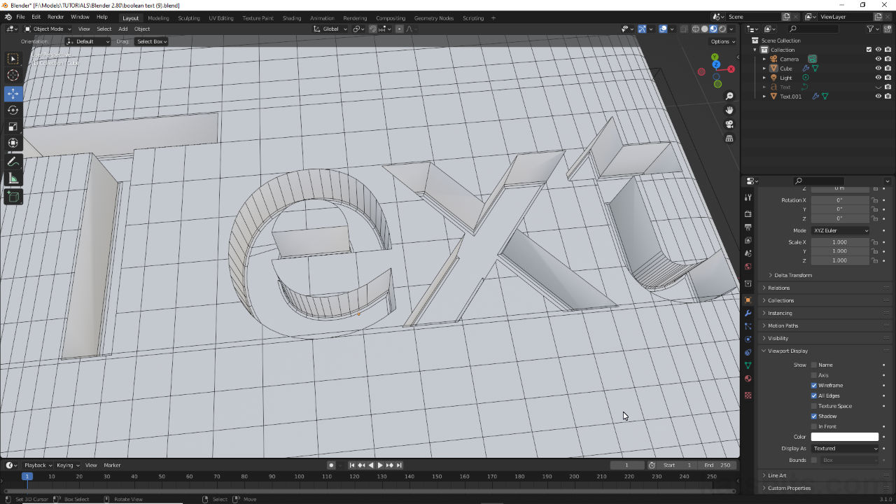
Adding a Decimate modifier [13] to the text mesh – wireframe display optionally enabled, Object Properties » Viewport Display » Wireframe, to highlight initial mesh structure after conversion.


In the modifier panel enable Planar [14] which will then reorganise the meshes structure more efficiently than the default conversion from text vectors [15].
For the object being cut the Decimate modifier typically doesn’t need to be assigned. Instead surfaces or structure can be cut or divided to accommodate the Boolean operation by isolating the area affected. Again however, the ability to do this depends on the type of interaction required and the complexity of both meshes involved in the operation [16]. With this in mind toggle into Edit Mode and use the various tools to add or remove edges, delineate structure, or isolate surfaces using inset to reduce the size of the face affected [17], changing the behaviour of the Boolean operation.


The initial interaction on an un-optimised mesh can result in divisions and segmentation that makes further editing tricky [16] (image-top), a problem that can be mitigated by adding loop cuts to limit the area affected by the Boolean operation [17] (image-bottom).
Bevel – Mesh
A common effect applied to text is Bevel. This can be done while the Boolean operation is still active or after Apply has been used to make the effect real. Bevel can also be applied using the Bevel Modifier or using the Bevel Tool.
Important: the degree to which Bevel can be used in this context is limited by mesh structure and the way that might be defined by the Boolean operation.
To apply the Bevel modifier to the live operation, select the object being cut by the text then in Modifier Properties click Add Modifier and select Bevel – Modifier Properties » Add Modifier » Bevel. A panel will appear in the stack and the mesh will bevel based on the defaults. Before adjusting the effect expand the Geometry sub-section and disable Clamp Overlap – this setting limits the degree to which the Bevel affects the mesh. Once disabled the effect can then be adjusted primarily changing Amount to decrease or increase the degree of Bevel, and Segments to increase or decrease the curvature of the a bevel through the addition of looped subdivisions.
Design note: with Clamp Overlap disabled the mesh explodes. To resolve this use smaller Amount values to compensate, e.g. change 0.1 to 0.01. How this affects the mesh also depends on the type of intersection being performed by the Boolean operation, Union for example may not explode the mesh as much when Clamp Overlap is disabled.
The affects of Clamp Overlap being disabled may differ depending on the type of interaction set between objects.


A common edit made to Boolean text is Bevel. Most simply by assigning the Bevel modifier [18] to the object being cut…

… which instantly bevels the mesh. To change the initial effect disable Clamp Overlap [19] and then alter the Amount and Segments values [20] appropriately to increase or decrease the complexity of edges bevelled.
By default when assigned to an object undergoing a Boolean operation the modifier affects all available edges equally. This behaviour can be controlled using the Limit Method setting. For full functionality however, the Boolean operation needs to be made real, which then allows for Vertex Group and Weight to be used in addition to Angle. To do this, first click the X in the corner of the Bevel modifier to remove it, then in the Boolean modifier click the ‘more options’ down-arrow and select Apply [21]. This immediately applies the effect and fixes the mesh.
Design note: while a Boolean operation is still live the mesh being affected by the modifier is still in it’s unaltered primitive state [iii] – the results of the Boolean seen in the 3D Viewport are essentially a ‘live’ preview of the effect once fixed in place using Apply (with Display modifier in Edit mode enabled in the Boolean modifier the effect is visible but uneditable in Edit Mode).
The Boolean operation may need to be made real using Apply before some Bevel modifier features work as expected [iii], the Vertex Groups and Weight options of Limit Method for example, else the underlying mesh remains unaffected.


To control where Bevel appears the initial Boolean operation needs to be made real clicking Apply [21]. This sets the change in place, mesh ready for Bevel.
Then for example, with the Boolean modifier applied to the mesh, in Object Data Properties create a vertex group and assign it to vertices or edges that should be influenced by Bevel [22]. In Modifier Properties reassign Bevel then set Limit Method to Vertex Groups and then Vertex Group to the group assigned to the mesh previously [23]. The mesh will immediately bevel, but only those elements assigned to the vertex group.

Once the Boolean is applied to the mesh, in Edit Mode create and assign a vertex group [22] to any edges that are to be affected by the Bevel modifier…

… then reassign Bevel and set the Limit Method to Vertex Groups and Vertex Group to the group assigned to the mesh – assigned and non-assigned edges shown above.
Bevel – Text Object
An alternative to applying the Bevel modifier to meshes directly is to implement it indirectly using a similar feature available to Text whilst it’s still in its vector form prior to conversion. Once this is fixed in place Boolean can then proceed normally as described above. To do this, once the basic properties of the Text object have been established e.g. changing Extrude to make the text solid, in the same Geometry sub-section is Bevel [24]. Click the heading to access the options if not already visible. Here increase the Depth value to activate the feature and add thickness, and subdivide the bevel by setting a Resolution [25] value to smooth or curve the bevel.
Design note: the bevel’s style can be changed clicking Round (default), Object or Profile.
Important: the bevel option for Text differs from the Bevel modifier in that it inflates objects, making them larger as the Depth increases, which in-turn changes the characteristics of the Boolean operation slightly [iv].
Adding bevel directly changes the characteristics of the Boolean operation [iv] and means more material is removed or added to the object being modified by the Text which also may need to be compensated for.


Text objects can be bevelled more directly using Bevel [24] instead of using the modifier…

… here simply increase the Depth value to activate the feature, and Resolution [25] to change the bevels curvature.
Changing Font
Blender doesn’t work with fonts in quite the same way as other applications. In this context, Boolean Text, fonts essentially loaded in as assets directly from the system font folder or other location in which they might be stored. To change font, drop in a Text Object as normal – Add » Text – then edit its basic appearance as needed, e.g. Extrude and/or Depth.
Design note: the fonts appearance and basic characteristics, as well as the Boolean operation itself, can be changed before or after font selection so long as the Text object hasn’t been converted to a mesh.
With text object selected, in Object Data Properties expand the Font options [26] clicking that subheading and then click the appropriate Open Font button to access and load in a font – Regular, Bold, Italic or Bold & Italic [27]. In the Blender File View that opens browse to the font, e.g. C:\\Windows\Fonts\, select a style then click the Open Font button bottom-right [28]. The selection will load into Blender and the text in the 3D Viewport will immediately change styled with the new asset [29]. The Boolean operation can then continue.
Design note: because fonts are vector-based objects (line art) Blender cannot style them after-the-fact as might be done in a text editor. In other words using a particular style means specifically selecting and loading that variation in using the corresponding Open Font button. This is organisational only and does not confer any special properties to the asset so a Regular font can be loaded into Bold & Italic even though it may not be.

Text objects use Blenders included font Bfont [26], which can be changed to any supported vector or line-art based *.TTF (TrueType) or *.OTT (OpenType) fonts…

… click the Open Font button [27] to load the file browse where the fonts to use are located. Select [28] and then click the Open Font button…

… which loads the selected font into the appropriate font slot [29], Regular, Bold, Italic or Bold & Italic, and changes the mesh in the 3D Viewport to use the new style.
Boolean Text & Subdivision
Using Boolean to indent, engrave or emboss text into subdivided surfaces should not in-of-itself be an issue where modifiers remain active [30]. Once fixed however, issues may manifest. For example, if Boolean is fixed in place before Subdivision Surface the results of the Boolean operation will collapse [31] as subdivision updates and adapts to the new mesh structure and shape. To avoid this ensure modifiers are applied in the correct order, Boolean typically being the last operation to fix in place.
Design note: this can also happen if the Subdivision Surface modifier sits below another modifier in the stack.

Where a Subdivision Surface modifier is assigned alongside a Boolean modifier the results of the operation remain intact so long as both are active/can be lived edited [30].

The order modifiers are fixed in place matters, applying Boolean before Subdivision Surface for example collapses [31] the effect of the operation because the subdivision then asserts itself over the new form.
Similarly if modifiers are applied but further editing needs to be carried out, for example adding a bevel effect using the Bevel modifier or bevelling manually, the effect will be limited by the density and structure of newly altered mesh, the bevel effect being applicable only so far as edge flow permits [32]. The only solution for this is to use Edge Slide or Vertex Slide in Edit Mode to reorganise edges and vertices to allow more room for bevel to occur without the aforementioned clipping or overflow.
Design note: bevelling works by subdividing and sliding along edges perpendicular to a selection based on how strong the effect is, the more an edge is bevelled the more room is needed to accommodate the change. When encountering a junction where edges meet bevel will attempt to continue but will typically fold over the junction causing collapsed faces and z-fighting.

Because subdivision tends to increase surface density, editing after-the-fact can be tricky depending on what’s being done, bevel for example is limited by edge structure and relationships, which can cause faces to malform and collapse or overlap [32].
