Knife
Table of Contents
For Blender 2.8+ Knife, the tool that allows cuts and divisions to be selectively (manually) placed on an object or mesh, remains ostensibly the same as it has been in previous versions with the exception that, alongside the reorganisation of the the interface, a dedicated icon in the Toolbar on the left becomes available when Edit Mode is active.
Design note: the Knife tools initial behaviour changes slightly depending on how its activated; using the shortcut, K, or the Toolbar icon. Using the former a (green) selection confirmation box appears highlighting the nearest vertex or edge alongside the knife mouse-cursor sprite (not shown), whereas the latter only shows the cursor sprite, the knife (not shown), the selection box appearing after the cut is started. In addition, using the shortcut key does not enable the Toolbar icon (its not switched ‘on’).
When Knife is initiated using the shortcut, K, the tool displays a highlight box that snaps to the nearest edge or vertex. This differs from initialisation by Toolbar icon.

Using Knife
Using the Knife tool is relatively straightforward for most applications; first select the object to be cut and then switch to Edit Mode (Tab). In the Toolbar to the left click the Knife icon – about 1/3rd of the way up the bar (from the bottom). The tool will initialise and the mouse cursor will change to a knife sprite.

Once Edit Mode is active and the Toolbar tools change to suit, the Knife tool will be available for use.
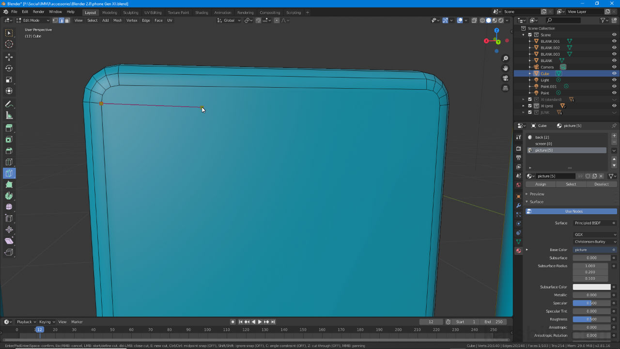
To cut, mouse over the object, a surface, edge or vertex, and click to initiate a cut [1]. A green node appears confirming the start or initial point of the cut. Move the mouse to a new location and click again [3] to place another ‘node’. Repeat to trace a ‘path’ [4], the ‘cut’ line (line along which a cut will occur) [2]. To complete press Enter.
Design note: Knife cuts are defined by the cut-line displayed between positioned (clicked and placed) nodes. To cancel press Esc or right-click if right-click is set as the default selection button.

As soon as the first cut point is placed a green box (outlined red) appears highlighting the location – this can be a random spot on a Face, and Edge or a specific Vertex, in each case the initial point is indicated.

After placing the initial cut a cut path [2] is then shown between multiple points [3], the cursor still displaying the tool [4] until Enter is pressed to complete the cut.
Closing a Knife Cut
To make a closed or loop cut, click around the mesh to place a set of node that define a cut path and that will also accommodate a closed path (avoid loopback). Then for the final node, mouse over the start point, an inset box will appear indicating coincidence (occupying the same location). Click this highlighted node, setting the path and closing the loop. Press Enter to confirm and complete the cut.
Design note: in this context a ‘loop’ is simply a manually defined path that ends on the same node from which it is started. Cutting arbitrarily shapes using the Knife tool generally, and more so where closed circuits are needed, tends to produce structure that’s not conducive to good edge or mesh flow, so some degree of reoptimisation may be necessary.

The Knife tool can be used to create ‘closed’ or ‘loop’ cuts, cuts that end where they start, by clicking out a node path to define a shape, the last point being to click on the first thus closing the loop (resultant structure, vertex, edge and face placement/positioning may require additional optimisation).
