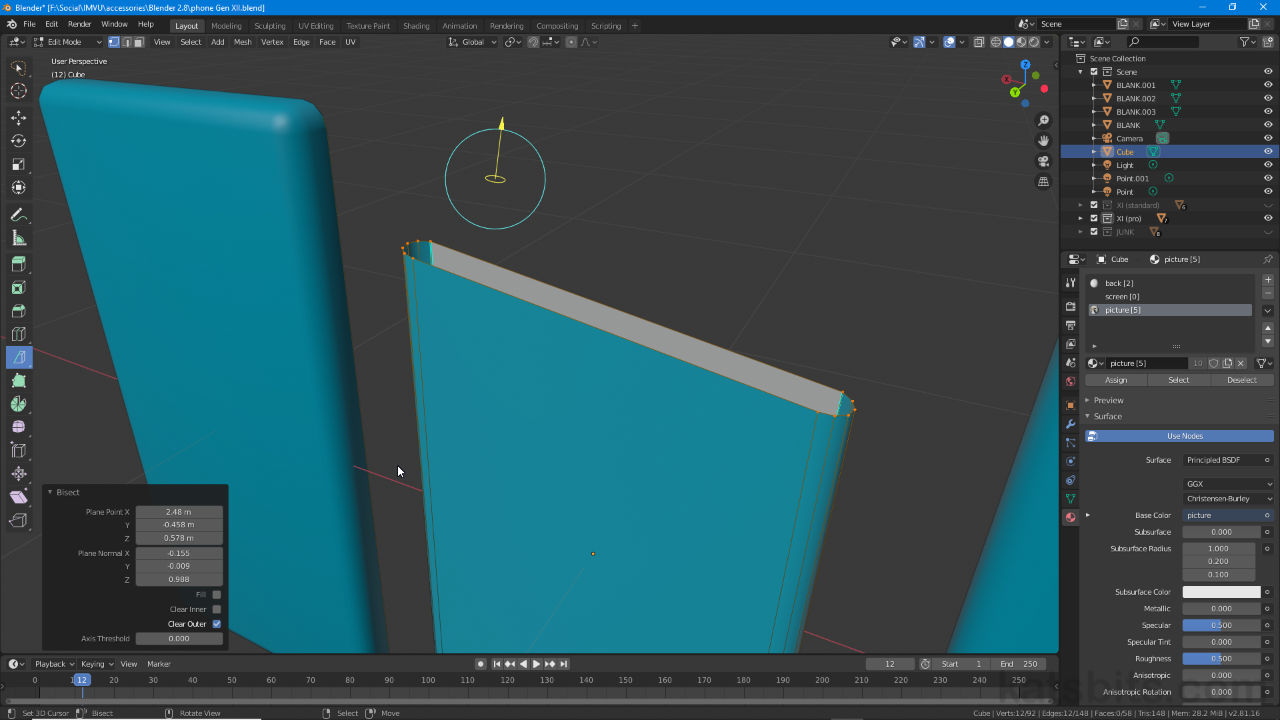
Bisect
Table of Contents
Where the Knife cuts selections, Bisect slices through them using a planar projection (flat plain) that’s orientated relative to the scene (viewport) cameras point of view. To do this Bisect first requires an active edge or face selection and then for the 3D View to be orientated with respect to how the User expects the cut to be made. Once the selection and orientation are set [1], in the Bisect context pop-up [3] a number of options can then be used depending on how the cut should be executed [2], e.g. to remove the ‘upper’ or ‘lower’ segments of the slice and so on.
Design note: Bisect is selection based, a warning will appear in the Status Bar of Blender if nothing is selected.

The Bisect widget [1] indicates the orientation of a slice (inner yellow circle) and also provides a way to make adjustments on the fly, to change the cuts orientation (outer blue circle) and position (yellow arrow).
Bisect (Knife » Bisect)
To use Bisect then, in Edit Mode (Tab) first make a selection, the edge(s) or face(s) to be cut (single vertices cannot be used), then click-hold the Knife button in the Toolbar and click the Bisect button in the fly-out (alternatively press Shift + Spacebar, then Shift + 2). Next manipulate the scene relative to the cut to be made and click-drag [4] across the selection [5] defining or describing the cut path or plain [6]. Release to confirm and set the cut [8], which is now made across the selected elements. The Bisect widget [7] also appears alongside the Bisect overlay [9] to facilitate further manipulation if needed (cf. below).
Important: at this point Bisect will have made a cut so unless this needs to be modified further, its orientation or position changed (cf. below), selecting a new element will deactivate the tool and return normal editing control over the mesh.


The Bisect tool is defined by a straight line relative to the view – click to one side of the selection [4] to be sliced and drag to the opposite side [5] to define the plain [6], the widget will then appear [7] with the active cut visible [8] and Bisect options overlay [9].
Bisect Options
To change how Bisect behaves, its position, whether sections of the mesh are removed or kept. In the Bisect options overlay that appear [10] click; Fill to cap gaps or close any open areas (subject to structural allowance); Clear Inner to remove one half of a cut, e.g. upper section of a selection; Clear Outer to remove the opposite or inverse of the cut, e.g. the lower half of a selection.
Design note: the Bisect tool currently does not require left-click, or pressing Enter, to confirm an action, instead select a new tool and/or make a new selection.
The relative position of the cut plain can also be adjusted altering the Plain Point to axially reposition the Bisect widget on the X, Y and Z or rotated around the same axes using Plane Normal, the widget ([7] above) representing the origin point for such. Once done select a different tool or make a new selection.
Design note: the degree to which the cutting plain can be moved or rotated will depend on its initial angle and orientation when placed; the mouse cursors location when clicked on-screen to initiate the path becomes the focal point of the tool, indicated by the widget itself.

Making adjustments to the Bisect cut by changing it angle (Plain Normal) and orientation (Plain Point) using the Bisect options overlay [10] that appears when the tool is active – the widget indicates the ‘pivot’ or ‘manipulation’ point around/from which adjustments are made.
