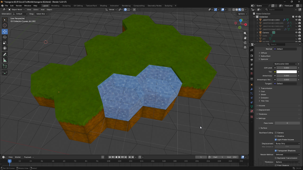
Hexagonal Grid Snapping in Blender
Table of Contents
Blenders native grid and snapping systems are defined though the equidistant subdivision of a base unit that can be a rounded or whole number, e.g. 1, 64, 111 etc., or a decimal or fraction, e.g. 0.326, 0.9, 0.0026 etc. In each scenario Blender accurately splits and distributes major and minor division of the grid. While this works exceptionally well for regular shapes and distributions, for non-uniform shapes like hexagons, two grids are effectively active at the same time, one for each axis. In practice, as Blender cannot natively support this, a custom proxy ‘grid’ needs to be created for use in conjunction with Snap (during transform).
Download: KatsBits – Hexagon Snap Grid Example (~500KB | *.zip).
Geometry Nodes – Grid Object
The most versatile way to create custom grids for object snapping is to use Geometry Nodes to procedurally generate a grid rather than using standard mesh/object Modifiers or repetitive mesh/object duplication because, once a basic grid unit is established, it’s then just a few mouse clicks to make the grid as large or small as needed.
Design note: hexagon base dimensions… [more]

The grid is designed around a hexagon that’s 2 x 1.73205 x 1 (W x D x H) metres. Any size can be used so long as the numbers and values are adjusted appropriately.
Grid Node
The first node to set up is the grid to be duplicated. This is procedurally generated using the Grid node. In Geometry Nodes Workspace and the Geometry Node Editor (lower area), click Add menu, find Mesh (about half way down the menu), then click Primitives, Grid – Add » Mesh » Primitives » Grid. A node appears with Size and Vertices parameters that define the grids basic structure. Here, for a hexagon (6 sides) generated from a 2 metre wide Cylinder primitive, set;
• Size X : 2
• Size Y : 1.73205
This matches the bounding box dimensions of the hexagon.
Design note: grid layout vs. grid shape… [more]

The shape of the grid isn’t as important as the divisions and subdivision as, barring one of two vertices of difference, snapping is almost identical.
Depending on how accurate or finite object snapping should then be relative to the grid, set;
• Vertices X : 5
• Vertices Y : 5
This subdivides the grid uniformly and equidistantly alone each axis, largely to accommodate the necessary hexagonal cell offset. To then use the grid, enable Snap (Shift + Tab) and set the Snap Target to Vertex (options set in the Header). Objects will then snap correctly to the grid, and each other, for hexagonal alignment.
Important: Blenders erratic behaviour… [more]

The Grid node defines the generated grid object that’s to be distributed. Dimensions are based on the overall bounding box of the hexagons the grid is the snapping aid for, not their physical shape, i.e. an actual ‘hexagon’.
Array Node
Once the grid node is set up defined, it needs to be duplicated. However, this requires two operations;
- The number of grid units duplicated.
- Their X and Y distribution or directional spread.
To achieve this an Array node is used. From the Add menu, select Generate, then Array – Add » Generate » Array. An Array node will appear that provides a number of options, primarily Count and Offset;
- Count: defines the number of instances generated by the node group.
- Offset: shifts individual instance positioning so grids don’t stacked atop each other.
Two of these nodes are needed;
- Array #1: defines the base unit and X axis distribution.
- Array #2: duplicates the base unit and distributes it on the Y axis.
Drop in a second Array node (Add » Generate » Array) and change the Offset values for each as follows;
• Array #1
– X: 0.000
– Y: 1.000
– Z: 0.000
• Array #2
– X: 1.000
– Y: 0.000
– Z: 0.000
Design note: alternative node setup & ‘Offset Method’… [more]
• Array #1
– X: 1.000
– Y: 0.000
– Z: 0.000
• Array #2
– X: 0.000
– Y: 1.000
– Z: 0.000
Both duplicate and distribute the grid but use a different ‘priority’ axis. Similarly, the relationships between base unit and replication can be defined using Offset, an alternative Offset Method. With this enabled instead of Relative (default), the Translation values for X, Y and Z differ accordingly;
• Array #1
– X: 0.000
– Y: 1.73205
– Z: 0.000
• Array #2
– X: 2.000
– Y: 0.000
– Z: 0.000
The generates the same grid and behaviour once correctly set up.

Using Offset instead of Relative establishes the same grid and distribution from a slightly different set up.
Finally, link everything together; connect the Grid nodes Mesh out to Array #1‘s Geometry input. Then connect Array #1‘s Geometry output to Array #2’s Geometry input. Finally connect the Geometry output of Array #2 to the Geometry input of the Group Ouput node.
([Grid] Mesh) » (Geometry [Array #1] Geometry) » (Geometry [Array #2] Geometry) » (Geometry [Group Output])
Once everything is linked up, simply increase or decrease the Count for each Array to increase or decrease the extent of the grid along the X and Y axes, e.g. a Count of 2 and 3 will spread the grid 2 ‘units’ up and 3 units along.

Using Array nodes to define how duplication and distribution of the base grid unit occurs. One Array controls the X axis, the other the Y axis, both creating an custom, hexagonal compliance, grid floor for oject snapping.
Geometry Nodes – Mesh Object
An alternative and more shape exact approach to creating a snap grid for hexagonal objects, is to use an hexagonal object as the base unit for the grid itself. Here, a simple ‘wire’, or vertex and edge only mesh, is replicated for snapping. However, because a none-regular shape is used, the rows needs to be offset before duplication. This means a Array node to define the X axis duplication, a second Array node to accommodate the offset, and a third Array to iterate the group into a grid.
Design note: hexagon dimensions… [more]
The grid is designed around a hexagon that’s 2 x 1.73205 x 1 (W x D x H) metres. Any size can be used so long as the numbers and values are adjusted appropriately.
Array Nodes (#1 & #2)
As the grids based unit is an actual mesh it doesn’t need to be procedurally generated, so a Grid node is not needed. Instead, in the Geometry Nodes Workspace, first make sure the hexagonal mesh object is selected in the 3D viewport preview, then in the Node Editor add the initial Array – Add » Generate » Array.
Important: Blenders erratic behaviour… [more]
First, set the Offset Method to Offset instead of Relative. In Translation values below, set the X, Y and Z values to;
• X : 0.000
• Y : 1.73205
• Z : 0.000
Connecting the Group Input, Array and Group Output nodes together through their respective Geometry inputs and outputs, if Count is increased, each hexagonal instance will be properly positioned along the Y axis, butting edge to edge. To then create the displaced instance so angled sides align, drop in a second Array node, again set to Offset. Here, the X and Y axes need to be set to push this second copy up and off to the side slightly, creating a diagonal formation;
• X : 1.500
• Y : 0.866025
• Z : 0.000
These two nodes form the base unit and similarly, when the Geometry inputs and outputs are link up, in increasing the Count of Array #1, the group is duplicated along the Y axis with in inherent hexagonal offset.
Design note: which nodes to use… [more]

The second Array should be used to define the ‘unit’ offset otherwise, if used generally, it generates a grid that’s not square or rectilinear.

Array #1 and Array #2 establish the base unit using an actual hexagonal mesh that is then instanced and offset to replicate the objects physical shape and how they (should) subsequently snap together.
Array Nodes #3
With base unit established and replicable along the Y axis, to duplicate it on the X axis, a third, final Array node is needed. Drop in another Array node set to Offset. Here, change the Translation values as follows;
• X : 3.000
• Y : 0.000
• Z : 0.000
With the Geometry inputs and outputs all linked together, changing Count on Array #3 duplicates the two-instance group along the X axis. In practice, the grids size is then defined by changing the Count values of just Array #1 and Array #3. To then use this grid for snapping, enable Snap (Shift + Tab) and set the Snap Target to Vertex. When objects are then moved, they will snap together based on the grid.

Adding a third Array node to the mix allows the initial node group to be duplicated along the X axis, the setup then able to form a uniform grid for object snapping.
Material Visibility
Geometry Nodes have a relatively higher priority over other object-level properties that mean ordinary Material or Modifier assignments not being fully honoured contextually. For example, assigning a material to the grid to affect it’s appearance has no affect on regardless of the Viewport Shading mode. In Rendered mode this is a particular issue because Display As properties like Wire (Object Properties » Viewport Display) are ignored in favour of rendering surfaces in flat white. To address this, materials must be linked up directly with the Geometry Node tree using a Set Material node that then references the appropriate material for display.
In Geometry Nodes Workspace, from the Add menu click Geometry, then Material, selecting Set Material from the available options – Add » Geometry » Material » Set Material. Drop this node between either; the Grid and first Array nodes;
[Grid | Mesh] » [Geometry | Set Material | Geometry] » [Geometry | Array | Geometry] …
Or between the second Array and Group Output nodes;
… [Geometry | Array | Geometry] » [Geometry | Set Material | Geometry] » [Geometry | Group Output]
The node works in either position. Once in place, click the Material input box, and from the list select the material to assign, e.g. snapgrid. The generated entity will then display based on the materials proeprties.

If Geometry Nodes are active, Rendered view ignores material assigned, which have to be connected directly to the node tree directly to be seen – above a simple 0% Alpha material hides surfaces while Wire displays the grid.
