Cycles, Transparency & Blender 4.x+
Table of Contents
Blender 4.(x)+ introduces a slight reorganisation of the material system interface. For the most part, while transparency itself remains functionally unchanged, they way each type is set up differs to a small amount from previous versions of Blender (Blender 3.6 and below). Updated for Blender 4.(x)+ then, how materials are created for the different types of transparency in Cycles render engine is outlined below.
General Changes
As briefly discussed above, Blender 4.(x) introduces a minor update to the interface; material properties and shader effects are essentially collated together by ‘type’ or ‘likeness’. In practice this means for Blender 3.6 or below, Material Properties lists options [1], whereas in Blender 4.0 and above, they are grouped [2].

Material Properties layout in Blender 3.6 or older – options are listed [1].

Material Properties layout in Blender 4.(x) and above – options and settings are grouped [2]
Similarly, Shading Workspace is subject to a few minor changes; Principled BSDF for example groups effect options [3] by type in Blender 4.(x) rather than listing [4] them as is done in Blender 3.6 or older. Menus are also reorganised in the same fashion, options again being grouped [5] by ‘type’ rather than their being listed [6]. None of this affects their functionality, just how they might be accessed.

For Blender 4.(x) and newer, material options are grouped in both nodes [3] and menus [5]…

Whereas in Blender 3.6 or older material options are listed in both nodes [4] and menus [6].
Cycles: Principled BSDF Alpha
The simplest way to set up a transparent material in Blender is to use the Alpha input property of Principled BSDF, which then affects the entire material. To set up, ensure the materials Blend Mode is set appropriately, e.g. Alpha Blend, then in Principled BSDF change the Alpha value; 0.000 for full transparency, 1.000 for full opacity (no transparency)
Important: for Eevee Blend Mode is in Settings as a sub-section of Material Properties, whereas for Cycles Blend Mode is a sub-section of a sub-section, i.e. Settings [i] section within Viewport Display [ii] options – Material Properties » Viewport Display » Settings » Blend Mode » [option]. Note also that fewer sort issues may occur when Cycles is used.
Unlike Eevee, for Cycles render engine, Blend Mode is located in Settings [i], which is itself inside Viewport Display [ii] of the selected materials properties (Material Properties).


Using a very basic material, and with Blend Mode set [7], transparency can be added by using the Alpha [8] property of Principled BSDF; changing this then alters the entire material making it more or less transparent or opaque.
Cycles: Image Based Alpha
Image-based transparency relies on the inclusion of alpha data with whatever image is being loaded into the Image Texture node; the A of a typically 24 bit RGB(A) (Red|Green|Blue|Alpha)bitmap.
Design note: the inclusion of an alpha channel does not make an image 32 bit, it’s 24 bit – 8 bit per RGB colour channel – plus 8 for the alpha. Alpha is not colour data.
To set this up, ensure the materials Blend Mode [9] is appropriately set, i.e. Alpha Blend, then in Shading Workspace place an Image Texture node and load in an image that carries alpha channel data. Link Color output to Base Color input, and for transparency, connect Alpha output to Alpha input [10] of Principled BSDF.
Design note: for image-based alpha the materials Blend Mode determines transparencies behaviour; Alpha Blend and Alpha Hashed for variable (grey-scale) transparency, Alpha Clip for transparency that’s defined by a black and white threshold (cf. Alpha Clip below).

Image based transparency uses alpha channel data that’s included within an image. With Blend Mode set [9], linking Alpha output to Alpha input [10] then defines the materials transparency.
Cycles: Opacity Map
An easier approach to using ‘alpha’ data for transparency is to use an opacity map. Typically a separate image that’s essentially transposing alpha channel data to equivalent grey-scale tonal values. When plugged into a material these tones then define the degree to which surfaces appear transparent or opaque – white = opaque, grey = variable transparency, black = fully transparent.
Design note: although opacity maps are often made and saved as a 24 bit images, in use they are typically down-sampled to 8 bit to better correlate with the 8 bit alpha channel data typical of image-based alpha (cf. image alpha above).
To do this, ensure the materials Blend Mode [11] is set appropriately, i.e. Alpha Blend, then in Node Editor (Shading Workspace) add two Image Texture nodes. Link the Color output from one to Base Color input of Principled BSDF and load in a ‘diffuse’ image. This is the image that’s visible. For the other node, link Color output to the Alpha input [12] of Principle BSDF and load in the separate opacity map. The materials transparency will update, as defined by the opacity map.
Design note: generally speaking opacity maps do not include alpha channel data by virtue of what they are, grey-scale images, so the tonal values have to be converted or transposed from ‘colour’ into ‘alpha’ or transparency. Connecting Color output to Alpha input facilitates this, the material then able to properly interpret colour data as degrees of transparency.

An opacity map is generally a separate image used to define the materials transparency, based on Blend Mode [11], and by link to Principled BSDFs Alpha input [12].
Cycles: Clip Mask
Transparency based on a clip or stencil mask is essentially the same image-alpha or opacity map based materials in that transparency is defined by image or alpha data with the exception of the Blend Mode used, Clip Alpha in this instance. Here a threshold can be set to limit how much of an image is rendered transparent or opaque.
Design note: clip masks and stencils typically use black and white images or corresponding alpha/no alpha data to define what should or should not be transparent, threshold then limits where grey tones that might be present as a consequence of aliasing, render transparent or opaque. This can also be used for full grey-scale images where the threshold effectively ‘cuts’ or ‘clips’ tonal data, rendering it transparent or opaque appropriately.
To do this, set up a standard material with Image Texture node and into this load an image that has an alpha channel. Link the Image texture nodes Color output to Principled BSDFs Base Color input, then similarly Alpha output to Alpha input [13]. Next, in Material Properties ensure Blend Mode is set to Alpha Clip [14] with an appropriate Clip Threshold value, typically 0.500. Once set materials will render transparent based on the image and threshold set.
Design note: if a separate image is being used to define transparency per an opacity map all that needs to be changed is the Blend Mode.

A clip mask or stencil like transparent material can be created linking up an image with alpha channel [13] and then setting the overall Blend Mode to Alpha Clip [14], with a Clip Threshold to define how aggressive the delineation is between transparent and opaque pixels.
Cycles: Transparent BSDF
For more complex transparency Transparent BSDF, in combination with a Mix Shader, can be used. Added to a material this node pair affords similar behaviour to Principled BSDFs Alpha property; Transparent BSDF essentially enables the effect, Mix Shader, the degree to which the material is then transparent.
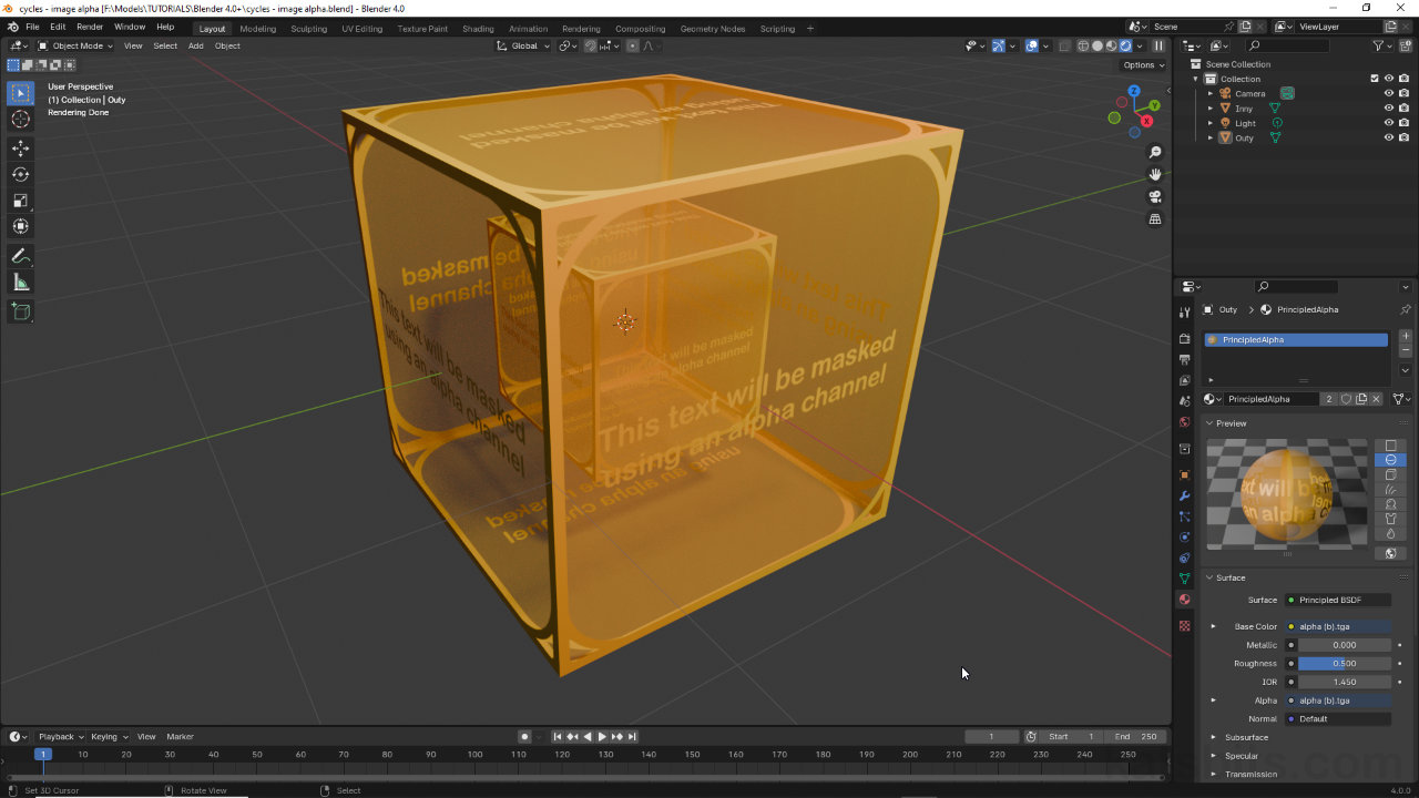
Design note: the addition of Transparent BSDF also means the materials overall transparency can be altered independently of any alpha data any images might carry, for example, an image with alpha channel data that defines a mask (Color or Alpha outputs linked to Alpha input) [iii], can be set up to stencil the image itself (see framed text shown below), when linked through a Principle BSDF node and a Mix Shader, can be faded despite the image-alpha [iv], a set up that could be animated to show/hide the material and image.
Augmenting image-based transparency with Transparent BSDF. Shown above, both cubes used the same image with alpha channel [iii] but one is faded as a consequence of using Transparent BSDF and a Mix Shader [iv].

To do this, in Material Properties ensure Blend Mode [15] is set appropriately, e.g. Alpha Blend, then in Shading Workspace drop in a Transparent BSDF and Mix Shader node, both found in Add » Shader » [node]. Connect the BSDF outputs [16] from Transparent BSDF and Principled BSDF to the Shader inputs of the Mix Shader, one output to one input. Next, link the Shader output from the Mix Shader to the Surface input of the Material Output node. Once everything is linked together the materials overall transparency can then be controlled alter the Mix Shaders Fac value – Fac: 0.000 for full transparency, Fac: 1.000 for full opacity (zero transparency).
Important: disconnected any direct link between Principled BSDF and Material Output; Principled BSDF should pass through the Mix Shader for this material setup to work correctly.

Transparent BSDF can be used to make a transparent material. Ensure Blend Mode is set [15] then link BSDF outputs through the Mix Shader [17]. Altering Fac can then be used to change the materials transparency.
