Vertex Colours & Texture Blending ASE Terrain Models In idTech4
The tutorial below covers the principles used when texture blending in Doom 3 powered games (currently Doom 3 itself and Quake 4), how models need to be set-up, how blending works and a rundown of the special material (shader) file the Doom 3 engine needs so it can work everything out.
Design note: useful command “r_showvertexcolor 0/1” to show/hide vertex colours.
The tutorial won’t however, go into the specific details on how you work with a 3D app to produce the model, or indeed D3Edit, so it’s assumed you know at least the basics of modelling objects in 3D, how to prep them for Doom 3, as well as understanding how to get them into the game itself.
The process described below is relative to the use ASE format models but applies to other formats able to store and use vertex colour information/data.
Similarities To Quake 3 Texture Blending
If you’ve done terrain or texture blending in any game powered by the Quake 3 engine then you will have used the same principles as Doom 3 texture blending employs. The Doom 3 process actually has more in common with Q3Map2’s ‘alphaMod‘ blending process than it does with the original Q3Map terrain shaders, but in either case, if you’ve ever used or looked at one or the other processes then you should find the Doom 3 method slightly easier in comparison.
Working With ASE Models
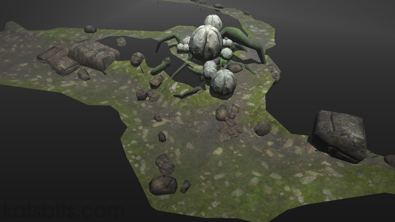
The image below is what we’ll be working with. It’s a section of a larger terrain model that has to be split away from the main object to allow for slightly better control over what textures get blended and where. Because of the way the blending system works it results in a limitations regarding the number of textures you can physically apply to any given mesh. More on this later
Design note: Where ever possible you want to be doing this process when the model is still based on quads not triangles. The reasoning behind this is purely for practicality; you need to be able to amend the mesh – either adding or removing polygons – as you paint the vertex colours. Invariably as you paint you’ll find certain areas work better than others which may require slight adjustments to the underlying mesh, in which case you want this to be as easy as possible to do; quads tend to be easier to edit then triangles.

A section of terrain shown textured in a 3D application. ‘Wireframe’ overview is enabled to highlight the distribution of polygons over this mesh object.
Mesh Density & Texture Blending Quality
As with texture blending for the older Q3 technology the quality of the results depend a great deal on the density of the mesh where blending occurs; the more polygons the better the blend. However, it’s not a good idea to simply add polygons to the model by doing a straightforward subdivision of the mesh ‘as is’. Instead, polygons need to be placed with more thought and consideration; where a good level of detail is required for the texture blending the poly count can be increased; where blending doesn’t occur or is not needed the poly count can be kept as it was originally or even reduced slightly to compensate for the increase in other areas.
Design note: In spite of Doom 3 being able to handle the average 60k+ poly count with relative ease, it’s always best to err on the side of the ‘lightest’ possibly solution in terms of the number of polygons on screen at any given moment.
Tiling Textures & UV Maps
As we’re using a ’tile-able’ texture similar to that used on brushwork – it’s not a texture that’s been created specifically for the model – it’s possible to be a little more ‘generous’ with the UVW map layout (see below).

Texture ratio between UVW map shown over the top of the terrain texture
A decision has to be made at this point regarding the relationship between the texture repeat – tiling, and texture resolution – how pixilated it looks in game; achieved by scaling the UVW map relative to the textures physical size. Exactly how much you do this depends on the physical size of the texture and how much pixilation you’re happy to see in game when viewing it close to.
The relative size of the UVW doesn’t effect texture blending, it just effects the resolution of the textures used.
Design note: Obviously be mindful of texture pattern repeat where the same feature tends to repeat more frequently (because you’ve increased the number of times the texture tiles over a given amount of space).
Vertex Painting
The actual control element of texture blending in Doom 3 powered games is done by the use of vertex paint. This is a method by which colour can be ‘painted’ onto the vertex points of a mesh. The mesh ‘remembers’ the vertex painted data when it’s exported, which the game then makes use of to physically blend the textures based on the vertex paint data stored in the mesh and the material information defined by the text in the games *.mtl file (more on this later).
The amount of texture blend in game is based on two
things;
-
The ‘density’ of the polygons in the area to be blended
As mentioned above, attention needs to be given to the distribution of polygons based on the texture blend effect you’re trying to achieve; if you need a ‘detailed’ blend in terms of the ‘shape’ the blend line follows (the level of detail the edge of a winding path has for example) then you’ll need to increase the amount of polygons over that area to allow for better ‘shape’ control.
-
The ‘strength’ of the vertex colour
By default vertex paint is generally ‘white’ (100%). For creating content for the Doom 3 engine, we basically only have access to two colours – ‘black’ or ‘white’. The strength or amount of opacity is directly related to the ‘strength’ of the texture blend in game; so the darker or more opaque the black or white, the stronger the texture blend will be in game.
Design note: ‘Gray’ is an indirect result of the opacity of either the black or white colour when painted onto a given area so although we only have access to two colours; black and white, we actually have access to the full ‘gray’ scale range between them; because we’re in 24 bit RGB that means 256 levels (tones) of ‘gray’ (from black to white).

Model section shown with ‘vertex painting’ visible – for texture blender black and white only
If you’ve been mindful of the design of your mesh object you will have constructed it in such a way as to increase the polygon density where you want to blend and decrease it where you want either one or the other texture to appear (none blend). When you vertex paint the mesh you’re taking advantage of this, the example mesh in this tutorial for instance, is slightly more dense where the black colour has been painted so in game blending creates nice strong edges and blended texture distribution in those areas.

Vertex painting shown over the top of the terrain texture in a 3D application window
Obviously what areas you paint depends on the textures you’re using and the topology of the (in this case terrain) objects. The black areas above indicate a worn gravel ‘path’ and the gathering of the same gravel in low lying areas of the ground surface.
Design note: You may find yourself going back and forth between vertex painting and editing the mesh so you get better placement and distribution of the texture/vertex paint relationship.
Exporting ASE Models
At this point – before the mesh is exported – you’ll have a fully UVW mapped model with a placeholder texture applied via the 3D application (a temporary texture used just to allow the correct UVW mapping of the mesh objects). The mesh will also be triangulated and have ‘smoothing’ applied to it.
Also, as mentioned in the section above, the mesh should also have vertex painting where necessary for texture blending and you need to make sure when the model is exported that the vertex colour information is kept in the file; although ASE and LWO files save the same data in different ways, the end result should be the identical.
Design note: Pre-Export check list;
- Depending on what you’re doing, you may find you need to cut the model down into smaller sections. These aren’t absolutely necessary but worth keeping in mind as you work on the mesh.
- Design note: ‘Smoothing‘ is functionally the same as ‘smoothgroups‘ in that they both use the same method of balancing the distribution of light over a polygonal surface. The only difference in fact is that a ‘smoothgroups’ is specific to a collection of faces or ‘grouping‘ – hence the name ‘smoothgroups’ – whereas ‘smoothing’ applies to a whole mesh object – it isn’t broken down into smaller groupings. For more info on this read the Doom 3 engine and smoothgroups tutorial here.
- Design note: Remember to triangulate and ‘smoothgroups’ the mesh before export.
Once you’ve ‘prepped’ the mesh it can then be exported to ASE (or LWO). After exporting, if you have a 3rd party model viewer, it’s a good idea to give the model a quick once over to make sure it’s exported correctly. Depending on what the viewer supports, vertex colours may or may not display when doing this.
It’s at this point that the mesh now needs to have a game specific material (shader) applied to it so it appears in game properly textured with blended images.
Basic Materials
The actual ‘control’ that tells the game engine what texture needs to go where is done via the material file ( the *.mtr) located in [x]base/materials/. Generally speaking, materials work in a similar way to Quake 3’s ‘shaders’ and for the most part follow some of the same principles; i.e. the use of ‘stages’ or ‘layers’ allowing a material to have several sections relative to the desired in game effect.
A standard material for Quake 4 (Doom 3 etc.) looks like the following and only deals with a single texture set; in most cases that holds information for just the diffuse and normal map images.
Design note: A good majority of the material files and references used in Quake 4 only have a normal and diffuse map; Raven didn’t go to the same extreme that’s present in Doom 3 by using all four images; specular and height maps are missing from many of the muted or metallic surfaces.
file/path/image(1)
{
materialType rock(2)
qer_editorimage file/path/image.tga(3)
diffusemap file/path/image_d.tga(4)
bumpmap file/path/image_local.tga(5)
}Design note: Although the above example is a very basic shader they can be far more complex in terms of what they do in game, especially when vertex particles and particles emitters are added. A basic breakdown of the above highlights follows;
- Material file reference – This is a ‘name’ that’s referenced on models to allow the textures to display
- Surface type – instructs the game what sort of surface it’s dealing with so it can then apply the relevant effects and decals for things like weapon impact hits etc.
- Editor Image – file path to a TGA image that displays in the editor (otherwise the black/red checker texture ‘shader not found’ will appear)
- Diffuse map – File path to the actual image used in game in terms of giving the player visual information about colour and details (so the player knows that a surface is ‘rusty’ for instance)
- Normal map – file path for the normalmap image that contains the physical characteristics of the objects surface detailing; groves, cuts, shapes and marks.
"file/path/image_[x].tga" denotes one of two things;
- If it’s in relation to item ‘1’ above then it’s not actually a ‘real’ system file path but a ‘name’ that is used as the material reference when editing models etc. It’s generally left as a file path for ease of use and doesn’t require 3rd parties to try and figure out where the assets for the material are physically located (without looking at the material file itself).
- In relation to other items it designates the actual physical file path to the location of the assets in the development folder; i.e. textures/widget/widget_local.tga is referencing the normal map being applied.
For texture blending we need a special material that can handle two sets of textures, each set being applied to one or the other of the vertex colours that were assigned to the mesh in the 3D application.
Texture Blend Materials
Now depending on what sort of visual effect you’re trying to achieve texturally, you can do a couple of things with the texture sets;
- Use two completely different texture sets and blend them together as separate ‘entities’. An example of this would be the blending of a dirt set and a metal column set so that each is only using assets from it’s own parent set; the metal support pillar only uses assets from it’s set and conversely dirt only uses assets from it’s set, creating a metal pillar with a grubby base as it rises out from the surrounding dirt.
- Use two partial sets where you mix and match different ‘layers’ between the two. A typical example would be using two types of gravel surface for the height, diffuse or specular maps but using the same normal map across both sets. This allows a common texture to be used ‘globally’ which gets altered ‘locally’ by the other layers (a side effect of this particular method keeps the final PK4 file size down slightly because you’re leave out the unnecessary images).
A typical material file for blending textures uses method ‘1’ (using two distinct texture ‘sets’) above and looks similar to the following;
Design note: as with the above ‘single’ texture set material file, the material example given below deals simply with the TGA image assets and does not include any ‘effects’ which can be added in the same way as mentioned in the design note above.
file/path/image
{
// << BLOCK A >>
qer_editorimage file/path/image_d.tga
materialType rock
noSelfShadow
// << BLOCK A >>// << BLOCK B >> TEXTURE SET 1
{
blend bumpmap
map addnormals( file/path/image_local.tga,
heightmap( file/path/image_h.tga, 8 ) )
VertexColor (1)
}
{
blend diffusemap
map file/path/image_d.tga
VertexColor
}
// << BLOCK B >>
// << BLOCK C >> TEXTURE SET 2
{
blend bumpmap
map addnormals( file/path/image_local.tga,
heightmap( file/path/image_h.tga, 8 ) )
inverseVertexColor (2)
}
{
blend diffusemap
map file/path/image_d.tga
inverseVertexColor
}
// << BLOCK C >>
}
As you can see from the above the material contains 3 ‘blocks’; ‘(A)’, ‘(B)’ and ‘(C)’.
- Block (A) is generally used to set ‘global’ parameters for the material that apply to all the ‘layers’ underneath it. Usually things like surface types (rock, stone, flesh, etc.), whether the object casts shadows or reacts to dynamic light (noSelfshadow, noShadows), and so on.
- Block (B) [coloured blue] is the first of our texture sets. The example above contains a diffuse, normal and height map.
- Block (C) [coloured orange] is the second of our texture sets. As with texture set 1 (Block B), the example above contains a diffuse, normal and height map.
Design note: As with single texture set materials the different stages don’t need to have the all 4 images from the classic Doom 3 texture set – diffuse, specular, height and normal maps. In the example above the specular maps aren’t used, and in many cases the heightmap can be removed as well (there are ways to combine the height image with a normal map in a photo editing application or by using any of the normal map tools freely available).
Generally speaking, in terms of their structure, the different stages of a blended material aren’t that different to single texture set material except in two significant areas;
- VertexColor
- InverseVertexColor
These two parameters are the ‘instructions’ that informs the game this particular material uses blended textures and that it should distribute each material layer accordingly; each one is assigned to one or the other of the two vertex colours painted onto the mesh, ‘black’ or ‘white’, and the difference in opacity between them determines the strength of the texture blend.
Applying Materials To ASE Models
As we’re using ASE models for this texture blending example it usually means doing a little bit of extra tweaking to the file because of the way ASE files are saved from 3D programs; usually the physical path to the images used during production are saved out with the model.
Open the ASE file into NotePad or similar text editor.
Design note: You may need to ‘assign’ NotePad to the ASE format; to do this do the following; right click select "File » Open with » Select program (or browse to NotePad .exe)". You can set NotePad to ‘Always open this file type’ by checking the checkbox under the available applications list, this will force ASE files to always open by default into NotePad.
Once the file has opened into your text editor you need to search for a line in the ASE called ‘*BITMAP‘; there may be more than one instance of this word depending on how many sections your model is composed of, but generally speaking it will look similar to the following;
*BITMAP "c:\projects\assets\models\widget\widgetbody.tga"
Design note: the file path will most likely be the location of your working directory, the place where all your project assets are; textures, models, etc.
The file path is the bit were interested in as that needs to be replaced with the material file reference which holds the texture blending information. In the sample material file above that’s simply;
"file/path/image"
Or in other words it’ll most likely be something similar to;
models/terrain/cliffs/rock1
Once you’ve got your material reference it then needs applying to the ASE file so it replaces the initial path saved with the file (shown above). Generally speaking Doom 3 powered games use material paths in the same way except in one instance; the location of the ‘main’ game content folder; with Doom 3 that’s ‘base‘, but with Quake 4 it’s ‘q4base‘ (the other upcoming Doom 3 powered games like Prey and Quake Wars may use yet different folder names; ‘qwbase’ for Quake Wars for example).
Go back to the ASE file and find the *BITMAP path again; it needs changing to the following for Quake 4;
*BITMAP "//q4base/models/terrain/cliffs/rock1"
And to the following for Doom 3;
*BITMAP "//base/models/terrain/cliffs/rock1"
Note the difference between each ‘base’ description, as explained above, this is important.
Design note: For more information on this see the prepping models tutorial and the "can I use ASE in Quake 4" editing tip.
Once this has been done the ASE model is ready for the next stage of development; getting the model in to the game.
Getting The ASE Model Into Game
Now by this point you’ll be ready to import the model into the editor where you can do the initial real-time render to check everything appears OK. Make sure the model and it’s assets are saved to a location associated with the material and files path therein referenced – not doing this is a common cause of models either not appearing or not being textured correctly in game. If everything has been done correctly when you press "F3" (rebuild "F7") you should see something similar to the image below; a correctly textured and rendered version of the mesh.
As you can see below, the two textures referenced in the material are blended exactly where they need to be based on the placement and distribution of the vertex painting applied to the raw mesh back in the 3D app used.

Texture blending section rendered in game

Close-up of the blend between the ‘grass’ and ‘gravel’ textures used in the test map

Mid ground view of texture blending
Error Checking
What sort of problems will be encountered? Thankfully not that many and the one that do happen tend to be related to ‘user’ error rather than a game error. The following list are some of the most common errors that happen when working with custom models in Doom 3 and Quake 4;
Material & Texture Rendering Problems
Generally speaking when any one of the errors below happens it normally means the material file info isn’t being referenced correctly, usually a simple typo or spelling error or putting the wrong file path in place. Click here for more details about editing ASE files for use in game.
-
Black model
Usually ascribed to a problem with the normalmap stage in the material file, it’s either going to be due to the image being ‘broken’ or the file path being incorrect, in either case the normalmap isn’t being found.
However, this error also happens when the model is trying to reference a material and texture that doesn’t exist (relative to how the model is looking for them).
In other words, if the ASE *BITMAP, material, and texture paths point to ‘body.tga‘ and you’ve actually got ‘boobies.tga‘ in the asset folder the mesh will appear black as it can’t pull in either the material or the texture image. As with the above, to fix this check the file paths are correct for the material and the ASE and that you have the texture image in the correct location.
-
Overbright model
Usually occurs when the mesh is accessing a texture directly from a folder instead of via the material. For example, if the *BITMAP path of an ASE was edited to;
*BITMAP "q4base/models/widgetsbody/body"
Design note: there’s no *.tga extension on the end of the path. Because the ‘path’ referenced in the ASE *BITMAP section is not a ‘real’ file path – it doesn’t necessarily refer to a physical location of an asset but instead to a ‘reference point‘ or ‘virtual name‘. As has been mentioned in other tutorials, the ‘path’ placed in the ASE is left as a ‘path’ simply for ease of reference in terms of making it easy to see where assets are at a glance.
And you had the texture physically used by the model in;
[path/to/game]models/widgetsbody/body.tga
You would find that if a material file didn’t exist for that model and image, the game would pull in the texture directly from it’s folder location bypassing any render information the game might need to display the image correctly. This results in the image appearing on the model ‘overbright’.
What’s actually happening here is that the game is being told it should be looking for and using a image called body.tga. If a material file exists that has a reference to the image via a physical file path as part of that material, then game will pull in the information it needs to render the texture image from there.
Example of a file path referenced in a material file;
diffusemap //q4base/models/widgetsbody/body.tga
If the material doesn’t exist, the game will pull in the image directly from it’s stored location, which in turn causes the overbright (fullbright) model because the game has no render information, other than an image from a file path; the material information is needed to tell the game how to render the image rather than just where it is.
-
Flat lit model
Similar to the above. An error in the material file usually resulting in the model not being rendered correctly. Check file paths, spelling and physical assets locations.
-
Inverted model (model appears to be inside out)
Again, similar to overbright models, there’s usually a problem with the material file being referenced. Check file paths, spelling and physical assets locations.
The exception to this is when the polygon faces of a model are facing inwards instead of outwards towards the game world. In such instances you may find the model is actually being rendered correctly – it’s not overbright – but it’s just displayed inside out.
To correct this the faces need to be ‘flipped’ in a 3D modeling program – if you can view ‘face normal’s’ turning that on makes it easier to see in which direction the polygons will be facing when it finally gets into game; face normal’s should point outwards perpendicular to the polygon itself.
Polygon & Texture Placement Problems
Generally speaking the errors mentioned below are usually due to there being some physical problem with the mesh or UVW maps. Correcting them requires reediting the mesh to fix wayward UVW maps. or gaps between polygons.
-
Sparklies
Thin lines that appear to ‘sparkle’ or ‘glint’ as you move around them. When the above happen it’s usually to do with the model not being finalised properly before export. It’s very rare for the game engine to render mistakes unless it’s something to do with the graphics card (usually a driver issue), so most errors of this type are to do with the model.
-
Gaps
Check that you haven’t left any gaps in the mesh, right down to the vertex level, as they will result in sparklies and/or gaps in game. Snap verts together to make sure they occupy the same co-ordinates.
-
Corrupt, wonkey or stretched textures
A UVW map problem to do with the distribution of the texture over the polygons the mesh is constructed from. Usually means reediting the UVW map on the model to correct any distortions.
Conclusion
You can’t blend textures over brushwork. Texture blending can’t be done over brushwork because the system makes use of vertex colouring, something that can’t be done in QeRadiant. Consequently modelled objects are the only way to use the vertex blending, so providing you can output to ASE or LWO files, both of which the Doom 3 engine can read ‘natively’, you should be able to create objects in game that have some degree of texture blending.

