Make Furniture Items for Frenzoo using Blender
Frenzoo’s own content is built with 3D Studio Max and as such everything to do with making furniture, scenes, items, accessories and so on, is dictated by how that application works in relation to their production process.
Despite this apparent ‘limitation’ it is possible to make items for Frenzoo using other 3D applications such as Blender, Maya and others, anything in fact that can export to Collada, via the FrenzooDaeConverter tool provided for that very job.
The following tutorial is specific to the use of Blender 3D to make furniture items for Frenzoo for sale in the shop or for personal use (‘template’ and animated items require a slightly different set-up that will be discussed in other tutorials). It will cover the preparatory steps necessary in Blender before exporting as well as the export process itself and how items are put together and submitted to Frenzoo’s ‘shops’.
Please note that it’s not within the scope of this tutorial to explain in any great depth or detail how to use Blender to make or model items, ideally you need to have a basic grasp and understanding of Blender before undertaking the following. You will also need to be using Blender version 2.48.1 or above.
Grid size & Frenzoo Scale
The first thing to do before starting any work, ideally, should be to set up Blenders global scale by changing the "Grid" settings in the "View Properties" panel. To open the "View Properties" panel click "View » View Properties". In the "Grid" section change "Spacing:" and "Divisions:" to "10" (or multiples of it the object is large). Increase "Clip End:" to "1000" or as far as it will go (left click drag) if making a very large scene – an outdoor area for example (please see additional note here).

Default grid scale in Blender is too small for Frenzoo

Corrected grid scale for Frenzoo furniture creation
Required Items to Make Furniture for Frenzoo
Although there are different ‘types’ of furniture items available for the making, all of them require a mesh object, an ‘item’ that’s visible in the chat viewer. The function associated with that item – how it’s used by the end-user in Frenzoo – can be changed and/or improved by the addition of the following;
- Avatar ‘nodes’ – a positional ‘marker’ so Frenzoo knows where to place the avatar
- ‘Attach Mesh’ objects – a non-visible surface used to ‘attach’ and position items together
We’re going to build a ‘stack-able’ furniture item (a large toy alphabet block) that has a single ‘seat’ node associated with it so the avatar can stand atop the block. For this product we need an object, an "Attach Mesh" and a seat node (shown below).

Shown in "Textured" view are the items required in Blender to make furniture products for use in Frenzoo. Using these items will create a ‘stack able’ object that can be stood upon

Above items drawn in "Solid" mode so each mesh object can be seen clearly

Wire frame mode of the above revealing the basic structure of the objects
Two of the objects shown above are self explanatory in that they are mesh objects; a ‘cube’ for the toy block and a ‘flat plain’ for the attach mesh (both of which will be explained later). The third item, the ‘pose’ node, is something called an ‘Empty‘ which acts as the position marker Frenzoo needs for avatar placement relative to toy block.
Open "frenzoo-toyblock.blend"
Download toyblock.blend here and then open it into Blender; top left, "File » Open", browse to where you saved the file, LMB click to select, then click "Open" top right – note that you need to be using version 2.48.1 or later to ensure the file opens correctly and its contents behave and work the way they should.
Once open you should see something similar to the image shown below; the main "3D window" on the left with a copy of the Frenzoo female avatar standing just in front of the toy block; the image used to texture the toy block on the right in the "UV/Image Editor" window; the "Edit Buttons" window across the bottom.

Opening the Frenzoo furniture sample file into Blender showing the 3D, UV/Image Editor and Edit Buttons windows.
As mentioned at the start of the tutorial we’re not going to go over how to make the block from scratch, instead we’ll use the sample block to look at how a furniture item needs to be set up correctly so it works the way it should in Frenzoo once loaded after being converted. So, lets get stuck in and look at how a model needs to be physically set up in Blender for correct export and conversion to Frenzoo.
Checking the Mesh is Set up Correctly
First things first, we need to ‘hide’ the Frenzoo avatar dummy so we can focus on the block without it getting in the way. On your keyboard press "1" to show just the layer the block is on (Shift+[n] selects more then one layer, or use the ‘Layer Buttons‘ bottom right of the 3D window), zoom in and press "Z" twice to view the model in "Wire frame mode", we’re going to take a closer look at the model, wire frame just makes the a little bit easier to do. Press the "TAB" key and enter "Edit Mode", you should see something similar to the following image.

Entering edit mode whilst in wire frame draw mode means the mesh becomes transparent so everything can be seen more clearly
Focusing on the 3D window for a moment, shown below is the block with a number of necessary areas highlighted; a set of red/green lines, a yellow outline and a pink spot.

Directional axis highlighted along with the point of origin objects need

Clean version of the above showing the scene ‘as is’
The first of these, the Red and Green lines that intersect the scene, serve two main purposes;
- They indicate an axis of orientation – a left/right or front/back direction.
- Where they intersect is the centre of the grid.
This is important for two further reasons;
- The axis effectively denote where an object should be placed in relation to a scene in Frenzoo.
- The centre of the grid is used as a reference point by Frenzoo as an item ‘locator’.
What this means is that objects need to be placed on Blenders grid relative to where and how the item is to be used in Frenzoo. For the toy block this means that right now it’s positioned in such a way as to allow it to be easily backed-up against a wall without intersecting, overlapping of getting buried into it; in effect, the Red line indicates where a wall would be so the block is placed as if it’s right up against the imaginary wall indicated by that red line.

‘X’ and ‘Y’ grid axis orientation
Next, the pink dot indicates where the objects ‘center point’ or ‘point of origin’ should be located, it’s important for Frenzoo so it knows how objects are supposed to be positioned in a scene when loaded. So using the grid and red and green axis, all items should be placed in Blender relative to that point, forgetting to do this could have items half buried in walls and floors because of misplaced origin points.

"XYZ" 0,0,0 centre point of Blender grid, also sets the ‘root’ origin point
Finally the yellow outline indicates the structure of the item. By default (and right now) the object is in something called ‘quad’ mode, although objects can be exported when like this it’s best to convert them into a more compatible format so as to lessen the chances of problems cropping up.

Quadratic (or "quad") triangle highlighted in Blender
Editing the Mesh Set-up
Reposition the mesh whilst it’s in OBJECT mode, click the arrows on the directional gizmo that appears after selecting the mesh (hold "Ctrl" to snap to the grid as you do this). Alternatively use the NumPad keys to change views and using "Top" (NumPad "7") "Front" (NumPad "1") and "Side" (NumPad "3") position the object where it needs to be, in this case that’s directly over grid centre as shown below. We’re going to turn this object into a standard ‘stack-able’ block.

Hold Ctrl as the object is moved so it snaps to the grid for easier repositioning
Centring or Repositioning "Object center"
As mentioned above, the object centre (point of origin or "POO" for short) – indicated by a small pink dot and generally where the gizmo appears when an object is selected – determines how an item appears and is placed in a Frenzoo scene. If you forget to position this point of origin before export you may find the item appears buried in walls, floors and other items because Blender used the original position of the POO when the mesh was exported. Because we’re working on an object that has to appear as if it’s placed on the floor of a scene or room, the POO will need to be adjusted relative to that. The most straightforward way to do this is to use the cursor as a target point and recentre the POO based on the cursors position.
To do this open the "View Properties" panel that should be visible bottom right of the 3D window (click the little ‘up’ arrow to the right of "x"), if it’s not, open it using "menu: View » View Properties". Find the section headed "3D Cursor" and change the "X", "Y" and "Z" values to "0" ("0.000"), you should see the cursor move as you do this.

Setting the 3D Cursor coordinates to change the position of the cursor
Once done, RMB click the block to make sure it’s selected and press the "Center Cursor" button in the "Mesh" panel in the Edit buttons window – if you can’t see that button press "F9" to display the "Editing" buttons window – you should see the pink centre point of the mesh jump to the location of the cursor; it’s now centred relative to the object as if placed on the floor of a room. All objects need to be treated like this in Blender before being exported out for use.

Using "Center Cursor" to re-centre the objects origin point to the cursor location
Material and Texture Assignments
Because we’re effectively trying to replicate what 3DS Max does in relation to Frenzoo content production, certain aspects of production in Blender (currently) require various work around’s to overcome issues that arise due to the differences between Max and Blender workflow. Material, texture and image set-up being one.
Ordinarily, a mesh would have it’s materials assign, each of those would have a texture slot and each texture slot would have a physical image attached to it. This is normally more than enough to simply export to Collada’s *.dae format, providing that’s a single object made from a single mesh. However, because of the way furniture has to be set-up to contain multiple meshes that must remain separate objects throughout the export and dae to efa conversion process, it presents a problem. Thankfully it can be fixed (more on this later).
For now make sure your materials, textures and images are set up correctly, objects must have UVW maps and any texture assets used need to be compatible with Frenzoo, so *.jpg, *.png and *.gif. You also need to check the "Map Input" panel ("F5" to open the "Shading" buttons) to make sure "UV" button is selected instead of "Orco"; this ensures the UVW maps applied to the mesh are exported correctly – this isn’t absolutely necessarily but does ensure there are as few sources of potential issues when exporting.

Make sure to select "UV" and not "Orco" as the map input
Apply Object Data
It’s likely that when making your furniture items in Blender for Frenzoo they’ll be incorrectly sized when imported into the client. This again, is due to our trying to replicate what 3DS Max does in relation to the Frenzoo workflow and in this instance, object sizing and measurements; it’s the number one reason why products appear too small in Frenzoo when imported. To fix this we need to use something referred to as "Apply Object Data" to ‘fix’ the size of the mesh; it’s here that the avatar dummy ‘helper’ comes in handy used as a fixed reference point to correctly size objects and items relative to the actual avatar itself; make a chair and know it’s the correct size; make a table and know the same relative to the ‘helper’. To see it press "Shift+3" to select the layer the dummy resides on.
Frenzoo avatar dummy helps maintain correct size relationships between furniture items and the chat client. As the block has been repositioned the avatar now stands at the centre of the object
To fix an objects size, select and resize it (keyboard "S" to "Size") relative to how big it needs to be in Frenzoo using the avatar as a guide. Once done press "Ctrl+A" to open the "Apply Object" pop-up and select "Size and Rotation to ObData", or from the 3D window header select "Object » Clear/Apply » Apply Scale/Rotation to ObData".

"Ctrl+A" to "Apply Rot/Size" to an object and fix it size relative to the avatar
That’s the basic prerequisites for the object mesh done. Next it’s the avatar spots and Attach Mesh.
Placing Avatar Nodes on Frenzoo Furniture
Avatar nodes, pose spots, seating node, or whatever you want to call the spot where the avatar stands are an essential part of any furniture you want the Frenzoo avi to interact with. Currently avatar spots are ‘generic’ for Blender made items in that irrespective as to the purpose and name, they only currently result in the avatar standing at a placed marker; again due to the way Max has been used for Frenzoo’s own content it means Blender and other 3D application users can’t place ‘sitting’ or other ‘animated’ pose on furniture items because other actions are parented directly to the animated rig of the avatar. Keep this in mind when placing avatar spots.
Avatar Spots in Blender are placed through the use of an "Empty", a directional marker that’s displayed as an "XYZ" gizmo, as shown below. To add an Empty to the scene, press the "Space" bar and select "Add » Empty", or in the "Add" menu at the top of Blender click "Add » Empty", both will place an Empty into the scene at the cursor.
Using an "Empty" as a marker where a Frenzoo avatar will stand
Three general things to note at this point.
First is the Empty’s size, it’s relatively small compared to other objects in the scene, that can make it tricky to work with. So to make it larger press "S" then "Ctrl" and resize the object whilst snapped to the grid (regulated increments in size). Or, use the "Size:" setting available in "Links and Materials" panel when the Edit buttons are visible ("F9"). In both instances resizing the empty has no baring on the avatars size in Frenzoo, it’s simply a position market.
Second is the Empty’s direction, not only does it provides relative ‘position‘ but also ‘direction‘ and ‘rotation‘, meaning the avatar will point where ever the Empty has been set up to point in Blender; the important axis to remember when placing is the "Y" "front/back" axis; the avatar always faces front when the "Y" axis arrow points backwards.

The avatar stands facing forward of the "Y" axis – the axis marker itself points backwards from the avatar mesh
Third is the Empty’s name. For Frenzoo to know that the object is support to be seen as an avatar node it has to use a specific naming convention using the prefix of "SP_"; this is important otherwise the node won’t work when the item loads into the client. To name the Empty select the object with the Edit buttons visible ("F9"), click in the "OB:" text field and type the name of the node with the "SP_" prefix, for example "SP_avispot" as shown in the image below.
Using "SP_" as a prefix for the name of the avatar spot
Attach Mesh Object
The third and final component that’s needed for furniture items is an "Attach Mesh". The Attach Mesh is basically a ‘primitive’ mesh whose surfaces are used by Frenzoo as a ‘locator’ onto which other objects can be placed in the client; our block for example has an Attach Mesh where the upper top face is, this allows other items to be stacked on top of the block.
It has a few caveats however, mainly that it cannot be too complex an object (usually a flat plain) and it must necessarily have a limited number of vertices per-mesh object, furniture items have a limit of 30 vertices per attach mesh object for example – keep in mind that you can join separate attach meshes into a single larger object. For more on the associated limits read the education centre post here.

The make up of an ‘Attach Mesh’ object needed for furniture items
When putting a furniture product together in Blender that have an attach mesh there are a couple of extra caveats that are again, the result of the differences between 3DS Max processes and Blender 3D. The mesh must have a material, texture and UVW map assigned to it, if not, it’ll appear in the client as a gray surface area as shown below (this is applicable to all objects in fact).

The Attach Mesh broken in the client and displayed as a visible gray surface
Setting up the Attach Mesh
The attach mesh is set up on furniture items in one of two ways;
- As originally part of the mesh.
- As a separate object.
Both have advantages and disadvantages.
As Part of the Mesh
it may not always be expedient to use in cases where an object is more structurally complex than necessary for the Attach Mesh itself, resulting in ‘waste’ – vertices and polygons assigned to the Attach Mesh that don’t actually do anything productive, thus using up the allotted allowance.
To add an Attach Mesh as part of this set up, select the object and enter Edit mode ("TAB"), then select the face or faces you want to use as the attach mesh – ideally they need to have materials, textures, images and UVW maps assign as mentioned above. Once done press "P" to "Separate", then click "Selected" from the pop-up menu, this will separate the selected faces from the mesh, creating a completely new independent object.
As a Separate Mesh
it means having to content with the fact that the object must have a material, texture and UVW map – something it would already have if it were already part of an object as described above. This means using some form of transparent material and texture.
To add an Attach Mesh as part of this set up make sure to be in Object mode then press the "Space" bar. From the pop up select "Add » Mesh » Plane", an object will appear where the cursor is. Resize ("S", then hold "Ctrl" to snap to grid) and re-position relative to the where objects are to appear to be attached.

Although the furniture Attach Mesh needs to be a separate object, that object can have originated from the parent object or be a completely separate object
Attach Mesh "AM_" Name Prefix
Either way the Attach Mesh must be a separate object within the final file exported to Collada. It must also use another naming pre-fix, in a similar to the avatar spot, this time "AM_", for example "AM_block" as the attach mesh used on the sample block model. To do this select the object and make sure the Edit buttons are visible ("F9"), in the "Link and Materials" panel click in the "OB:" and type "AM_" plus the name of the object as described above, so "AM_block".
Design note: The Attach Mesh can have any name, just so long as it’s pre-fixed with "AM_".

Attach Mesh objects need to be named with the "AM_" prefix
Attach Mesh Position
As the Attach Mesh is just another mesh object how it’s positioned relative to the main item is important, this is especially true of its origin point, which needs to be located in the same place as the main mesh body; as all mesh objects are exported relative to their respective origin points they should all be in the same location so there aren’t any misplaced or mismatched objects when it’s loaded into the client.

Correct positioning of the Attach Mesh origin point relative to the main mesh
Detached faces and Attach Mesh origin position
If adding an Attach Mesh that was a detached face as mentioned above, the origin point is likely going to be in the came (correct) position as the parent object so nothing more need be done at this stage (if not see below).
Separate Object & Attach Mesh Origin Position
If adding an extra Attach Mesh separate plane then it’s origin point will need repositioning using the same process used to reposition the blocks origin point mentioned above.
Alternatively, select the main object and press "Shift+S", in the pop-up that appears select "Cursor to Selected", the cursor will jump to the blocks current origin point (which was set above). Next select the Attach Mesh object, then press the "Center New" button in the "Mesh" panel of the Edit buttons window, the Attach Mesh’s origin point will jump to the location of the cursor.
Using the "Center New" button to re-centre the objects origin point to the cursor location after that’s been centred on the parent mesh using "Shift+S"
Attach Mesh Material & Textures
Ideally, and depending on which choice you make in creating the Attach Mesh, it will need a material as mentioned above. This means that if the Attach Mesh originates from the object (as a detached part), it’s best to do that after material, texture and UVW maps have been applied to the model, that way there’ll be a 1:1 correspondence between the main body of the model and the detached face.
If on the other hand the Attach Mesh is formed from a entirely separate object, then its going to need a transparent texture applied to it so it’s not visible in the client and doesn’t show up ‘broken’ (gray). This can be taken advantage of actually, with the image applied acting as a ‘shadow’ which would appear under objects, obviously it may look odd when objects aren’t stacked.

An image made in Corel Photopaint showing a shadow mask used as a transparency applied to the Attach Mesh in Blender
Shown above is one such ‘shadow’ texture. The shadow itself can be seen as the gray blur over the white background on the left (white just makes it easier to see). The background is then filled with black and the active object – the shadow – is converted to a ‘mask’; by making the background black before converting to a mask and flattening the image, you eliminate ‘halos’ that are common to transparent textures whereby the masked object picks up the underlying background colour around it’s edges – always, where possible, use the same colour for the background as the masked object.

Shadow texture applied to the Attach Mesh object. The image has an alpha mask making it transparent which Blender renders using the UV ‘Alpha’
Whilst doing this, or not, has no direct effect on the subsequent export of a model, it’s a useful feature to use in Blender whereby images applied to texture slots can be ‘forced’ to render as transparent (if they have an alpha channel that is) in the 3D window. To do this select the object and enter "Edit" mode ("TAB"), select all ("A") and make sure Edit buttons are visible ("F9"). Find the "Texture Faces" panel (often hidden behind other panels) and click the "Alpha" button, this will force the selected faces to draw transparent. The final step is to then click the "Copy" button to force the transparency applied to the initially selected face across the entire selection of faces UVW mapped with the alpha’d image.

In Edit buttons whilst in Edit mode, transparency can be forced render using the "Alpha" button from the "texture Faces" panel
Prepping for Export, Putting Objects Together
At this point the scene should consist of a block (primary mesh object), an avatar spot (an Empty) and an Attach Mesh (second mesh object) positioned and ready for export to Collada’s *.dae format. Before doing that however, there are two essential last steps that need doing to all mesh objects that form the Frenzoo furniture item; "triangulation" and "mesh smoothing".
Triangulation
Polygons can be represented in any manner of ways in 3D applications so in order for Frenzoo to render what it sees properly all faces/polygons need to be broken down into their composite triangles, this ensures the mesh is rendered exactly the same way it was in Blender, on complex shapes, breaking the mesh like this can flip triangles incorrectly which aren’t noticed until the object is in the client.
To triangulate the mesh, enter Edit mode ("TAB"), select all ("A") and then press "Ctrl+T" which should result in all the faces of the mesh splitting along the diagonal as shown below. If doing this on a complex model you see faces cave inwards, select the offending faces ("Shift+RMB") and use "Ctrl+Shift+F" to ‘flip’ the faces around to fix the problem.

Tessellating (triangulation) of the mesh prior to export to Collada and Frenzoo
Smoothing
An object like the sample block of this tutorial doesn’t necessarily need smoothing because it’s a ‘box’ and those usually have ‘hard’ edges. You can read more on ‘smoothing’ here and here but essentially what it does is distribute the way shading and light falls across the surface of a model to give a ‘smooth’, ‘soften’ or ’round’ appearance, ideal for curved, round or organic shaped objects.
To add smoothing to an object you need to be in Object mode. Select the item in question and make sure the Edit buttons window is visible ("F9"). Press the "Set Smooth" button in the "Link and Materials" panel.
Design note: If you need to control smoothing, i.e. you need a hard edge on an object somewhere, switch to Edit mode and then switch "Select mode" to "Edges" ("Ctrl+TAB", select "Edges" from the pop-up). Once in that selection mode RMB click the edges you need to be ‘hard’ and press "Ctrl+E", from the pop-up select "Make Sharp". Exit Edit mode once done to find ‘marked’ edges sharp/hard.

Adding smoothing or smooth groups to a furniture object in Object mode
Exporting to Collada *.dae
Exporting the objects from the Blender scene to Collada is relatively straightforward, simply select the individual items, making sure that the main mesh is the last one selected so that takes hierarchical priority in the *.dae file that will be made (it’ll be outlined a brighter pink), then from the File menu select "File » Export » Collada DAE 1.4" – make sure to use the 1.4 exporter. The screen below should appear. Make sure "Triangulate", "Only Export Selected", "Use Relative Paths" and "Use UV Image Mats", this last one, "Use UV Image Mats" is important when exporting multiple mesh objects, especially when there are multiple objects in the scene making use of the same materials – more on this below.

Settings to use when exporting objects form the Blender scene to Collada which will then be converted to efa files using FrenzooDaeConverter.exe
Right now the only way to get a efa file loaded into Frenzoo correctly it needs to be structured in a particular way, so although you can export any manner of mesh and object then need to adhere to one or more of the following ‘rules’ with regards to objects and materials.
- All mesh objects need separate materials.
- All mesh objects need individual texture images even if the AM_ mesh is formed from simply detaching a section of a ‘parent’ object, as mentioned above.
The images below show the block set up and export relative to what’s been discussed above. In other words, the first set of images show the AM_ mesh exported with its own UVW map, material and texture. The second show the AM_ mesh exported using the same texture as the main mesh (of which it was originally part).

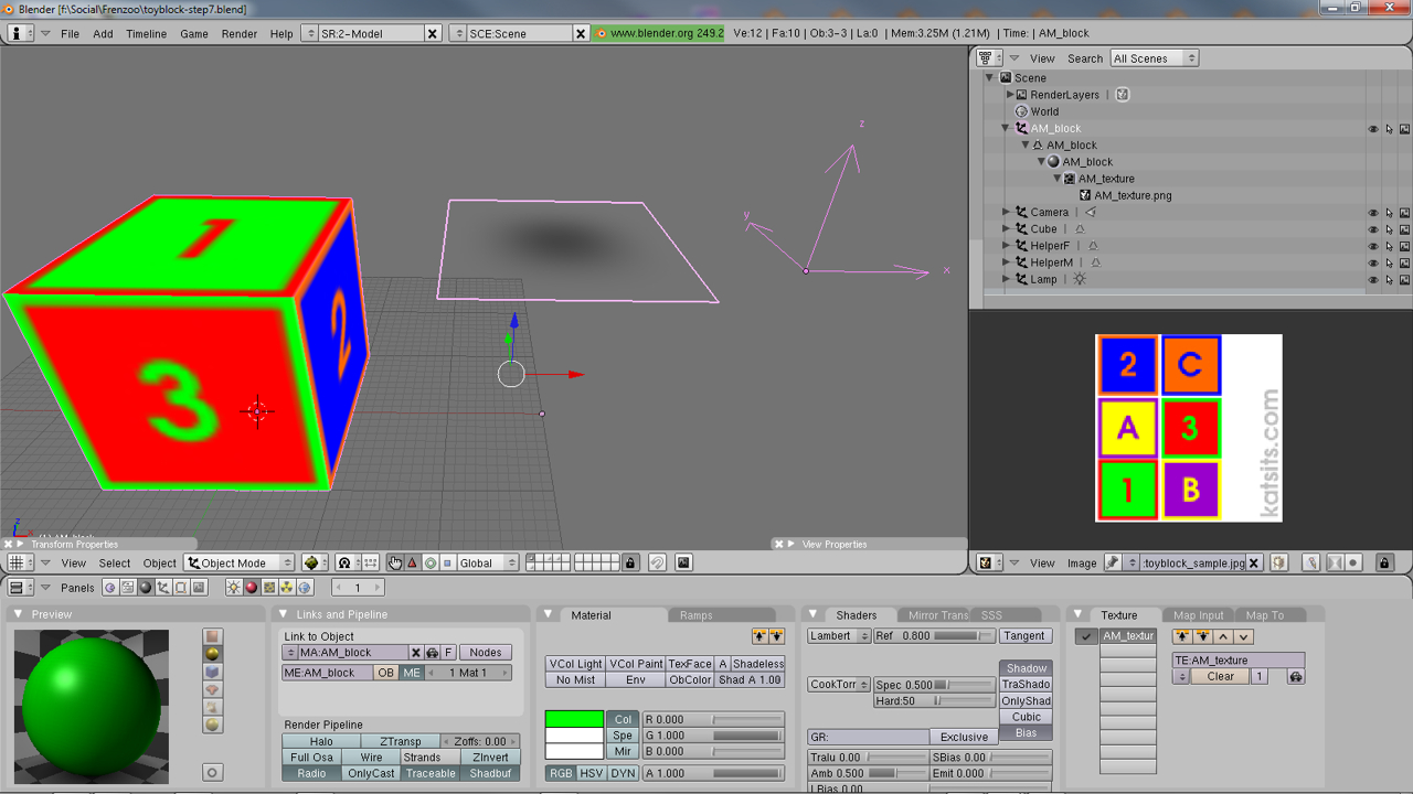
AM_ mesh exported using a different set of material, texture and image assets than the other mesh object (the block)

AM_ mesh exported using the same texture image as the main mesh
The results of these two different approaches is shown below. The first works, the second doesn’t, neither is ‘correct’ in the literal meaning of that word, but only the setup where the AM_ mesh is in effect ‘uniquely’ materialed and so on actually imports correctly. It’s not possible to export a ‘blank’ mesh either as that results in a similar issue as is shown in the second image below.

Toy Block object loaded into Frenzoo where the AM_ mesh was exported using its own set of material, texture and image assets
Toy Block converted efa and loaded into Frenzoo using the same material, texture and image assets as the main mesh body. Frenzoo can’t read the results
Convert Collada *.dae files to *.efa Frenzoo Furniture Items
There are a couple of differences between doing a basic *.efa conversion of a Collada *.dae file where furniture items are concerned; primarily with regards to the ‘type‘ of object being converted and its size. As the export process has been covered before we’ll instead discuss the specifics of processing furniture items in this instance.
Normally when converting dae files to efa’s, the command used in the CMD prompt would look like this;
FrenzooDaeConverter.exe mycolladafile.dae mycolladafile.efa
For furniture items however, two new commands need to be added;
- -scene_type=scene_item
- -unit_meter=[value] (optional)
The full command line looking similar to the following;
FrenzooDaeConverter.exe -scene_type=scene_item (-unit_meter=[value]) mycolladafile.dae mycolladafile.efa

New commands for the CMD prompt to convert dae into efa files
The ‘-unit_meter’ parameter is optional and only required if the avatar dummy helper has not been used as a fixed reference for scale and size in Blender. If it has the command looks like the following;
FrenzooDaeConverter.exe -scene_type=scene_item mycolladafile.dae mycolladafile.efa
If it hasn’t been used, to correctly size objects relative to Frenzoo type the command line below, substituting "[value]" with "0.032" (or other value) so the command line looks similar to the following;
FrenzooDaeConverter.exe -scene_type=scene_item -unit_meter=0.032 mycolladafile.dae mycolladafile.efa
It’s recommended that objects are sized in Blender relative to the dummy before being exported, if this isn’t done expect to spend more time experimenting with unit values to approximate a 1:1 match in Frenzoo that may change the next time a new item is made and exported.
Conclusion
Much of the above has been written based on the way Frenzoo worked at the time of writing, meaning that at any time in the future the structure and process to prepare, export, convert and import Blender made items into Frenzoo may change without notice. Having said that however, the basic principles should remain the same, in that the following checklist of items should be valid;
- Collapse multiple materials used over multiple objects.
- AM_ mesh object are best dealt with as individual objects and not as originating from any part of the main modeled object, least that mean duplicating content.
- Furniture items don’t necessarily need and AM_ or avatar spot.
- Items don’t necessarily need to be parented unless animation is involved in the product.
- Texture images should be below 256×256 pixels, anything above is considered ‘large’ in Frenzoo.
Notwithstanding any obvious errors, making content for Frenzoo with Blender is pretty straightforward once the basic principles involved are understood. You can read about some common errors and problems here. Once the Collada file has been export and converted to Frenzoo’s *.efa format, it’s just a matter of uploading the newly created item into the shop via the 3D Pro upload page and a web browser.

