Export ASE Models From Blender 3D
Meshes can be exported from Blender as “ASE” (“Ascii Scene Export“) models using an export script. The format is supported by a number of mod-able games including Unreal/UDK, idTech et cetera, as well as being an easy-to-use format non-proprietary content can be exported to for general game development usage.
Whilst the actual export process itself is reasonably straightforward, meshes do need ideally need to follow a number of basic rules if they are to load and work correctly in a game or editing environment; exporting a simple cube with a single texture is not quite the same as exporting an actual game ready model with all the complexities of using multiple meshes, materials, textures and UVW maps, something that’s far more typical of making custom models and content for games.
Resources: useful links to accompany the tutorial below;
– Download ASE script.
– Installation ASE export scripts.
– Learning Blender
The following tutorial discusses the main considerations to keep in mind when preparing and exporting ASE models from Blender, as well as explaining some of the issues and more advanced concerns that need to be observed whilst doing so. A basic understanding of Blender is assumed.
Design note: the process explained below can also be used to export (static map object) models from Blender 3D to other formats and not just ASE, the principles are generally the same irrespective of model format.
Initial scene/model set-up
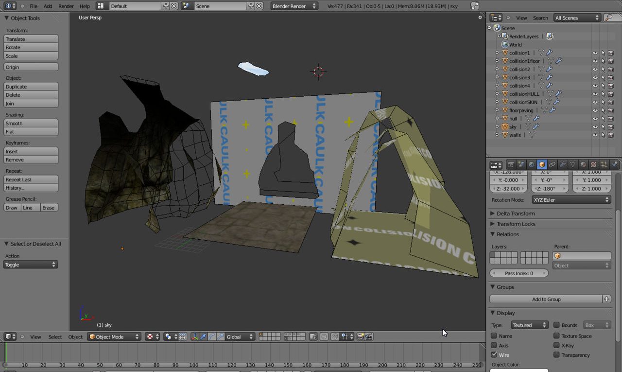
To explain the process of exporting ASE models from Blender properly and in sufficient detail we’re going to prepare and export the object shown below, a relatively complex rock-walled corridor map-object (previously used in the setting up collision hulls tutorial) composed of a number of separate elements – a “rock” section, a “floor” section, “sky”, “hull”, and finally a “collision” section. Each individual object has it’s own individual material, texture image and UVW map applied so there are five separate “Object“, “Material“, “Texture” and “Image” references being used. This is and should be the initial state from which to export.

The individual elements that go into the making of a typical game object; each item is a separate ‘object’ with it’s own material and texture.
The basic mesh export procedure
The actual export process tends to require the following preparatory steps be done before a mesh can be exported from Blender to ASE or any other model format for game use. If not, or if any steps are missed, there is and increased likelihood the model may not exporting, or may export incorrectly. They are;
-
Make sure meshes have Material, Texture and Image assignments
One of the main sources of problems with ASE and other models exported from Blender. Make sure all objects have at least one Material, Texture and Texture Image assignment. Learn more about materials. [advanced] [problem?]
-
Make sure mesh objects have UVW maps applied
As with Materials, make sure all objects to be exported have at least one UVW map present. Learn more about UVW maps. [advanced] [problem?]
-
Remove unused material assignments
Always remove unused or rogue material assignments (this applies for both Blender ‘datablocks’ and physical assets). Learn more about removing materials. [advanced] [problem?]
-
Collapse mesh
Be sure to properly set up object hierarchies relative to there being either a single mesh/multi-material or sub-objects/multiple-materials, they are NOT the same. Select all and “Ctrl+J” to JOIN items together into a single mesh. [advanced] [problem?]
-
Select object(s)
Related to “Collapse mesh” above, if an object containing ‘sub’ objects is required, select all meshes prior to export, making sure that at least one is the ‘primary’ object – DO NOT join meshes together in this instance. [advanced] [problem?]
-
‘Fix’ object position
Make sure to correctly position all objects relative to their intended use. Select and position objects, then use “Ctrl+A” to fix “Location“, “Rotation” and “Scale“. [advanced] [problem?]
-
Centre objects point of origin at grid 0,0,0
Related to the above, be sure to correctly position all objects relative to Blenders grid centre (“0,0,0”) and the eventual intended use of the exported object. Select and position objects, position cursor then use “Shift+Ctrl+Alt+C” to set origin relative to requirements. [advanced] [problem?]
-
Triangulate all mesh sections
For most games, a REQUIREMENT. Meshes should be manually “tessellated” however. Select meshes individually and use “Ctrl+T” to triangulate. [advanced] [problem?]
-
Export
Depending on the version or format of used export script, check appropriate parameters; if “Scale” is present, make sure that “1:1” (or “1.000“) means models are exported the same size as they appear in the scene (this will mean using some form of sizing template in Blender). [advanced] [problem?]
Conclusion
As is typical when exporting any form of content from Blender for use in game development, all manner of issues and problems can occur that are not directly related to Blender or its output. However, so long as the above steps are followed and the technicalities of game production are kept in mind (read the advanced section for more on this) it aught to be relatively straightforward to sort out problems when/if they do occur; the ASE format, being text based, is quite versatile, often requiring nothing more than an amend in a text editor.

