Make IMVU Rooms Using Blender #3 – Prep & Export
In the third part of "Making IMVU furniture rooms in Blender" a Scene, containing a room Mesh and Armature objects, will be prepared and then exported to Cal3D and the four basic XML files – "*.xmf (Mesh)", "*.xrf (Material)", "*.xsf (Skeletal)" and "*.xaf (Animation)" – needed by IMVU for assembly in Create Mode.
Download: Katsbits IMVU Room Template (c. 1.5 MB | *.blend, *.xsf, *.xmf, *.xrf, *.jpg).
Note that if a room has previously or by other means been exported and the necessary Cal3D files are already available, this section can be read as stand-alone instructions on putting everything together in Create Mode.
It is recommended the entire tutorial be read so as to fully understand the context of export however. Familiarity with Blender is also necessary so if this is not the case read through the following tutorial to learn the basics of using the application to model a simple chair.
Exporting To IMVU
The process of exporting meshes from Blender to IMVU generally tends to be the same irrespective as to what the mesh is as a product; the same basic procedures are used to prepare, export and assembly a room as are used on a bubble-pipe.
The only real difference is just in their end use and functionality in IMVU.
This basically means that for a fully function custom product, and to ensure the correct files are produced, there needs to be a Mesh – which will be the "XMF", an Armature – the "XSF", at least one Material – the "XRF", and a simple Animation with at least a single frame – the "XAF".


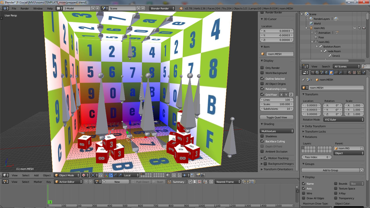
The template room ready for export from Blender (top) and Blender 2.49 (bottom) to IMVU – the textured room mesh, in which all objects are joined together, is parented to the Armature, which in-turn has an animation "Action" assigned, the whole then being ready for export
Export Checklist
At the point of getting ready to export the content of a Blender Scene a majority of the work necessary to make a room is done. All that remains is to double-check the relevant material and parenting relationships, and add an "Action" before final export. To assist in doing this it helps to have a check-list to hand as, whilst using one might not necessarily avoid unforeseen problems, they do help in avoiding common issues that crop up as a result of neglecting to carry out one of the more obvious steps in the procedure.
For Armatures the general checklist is as follows, check that;
- the room Armature should be positioned centrally on Blender grid
- Armatures should be joined into a single unit
- bones are correctly named and number per their function
- bones are correctly orientated or rotated relative to their expected function
- bones occupy the proper position in the overall Armature hierarchy
- the Armatures position is reset and ‘zeroed’
- the Armature has at least a single framed "Action"
For Mesh preparation the checklist is generally to make sure that;
- meshes are joined into a single unit where appropriate
- meshes are UVW unwrapped
- the room mesh contains at least one full material slot with texture
- at least one texture is assigned to the UVW map
- the room mesh has at least one vertex group assigned called "skeleton.Room"
- the mesh should ideally be triangulated before export (optional)
- the room mesh is properly parented to the room Armature
Important: because meshing with Blender is an extensive subject some of the above points are covered in greater detail separately. For more resources read the following excellent tutorials which teach how to use Blender – "Learn to make a basic Chair in Blender 2.49", "Learn to make a simple chair", "Learn to make a simple Sword" and "Learn to make a Simple Character".
Armature Preparation – Joining, Parenting Etc.
At this point in production it’s likely the rooms Armature may still be in sections, each will need to be joined to the main ‘root’ Armature, "ROOM.RIG" when using the room template for example, before export as it’s not possible to select, export or use multiple armatures for the same room unless they are components of the room. The order in which Armatures are joined together is important, when selecting multiple objects ensure the ‘root’ component, the Armature containing "skeleton.Room" is the last element selected (it should highlight a lighter colour to indicate this) then use "Ctrl+J" to "Join" them or access the ‘confirmation prompt’ in Blender 2.49 before further clicking "Join selected armatures" to confirm the action, joining them together into a single larger object.
Design note: a room can contain a number of armature elements but only one can contain "skeleton.Room" – a complicated or long animation sequence for example might be better utilised if all the elements used are exported as a separate unit within the overall room thus cutting down on the number of bones which have to be frame marked.


When joining Armatures be sure to select the ‘root’ section last so it highlights a lighter colour to ensure proper hierarchy set-up. In Blender simply select the object in order and use "Ctrl+J" to "Join" them together. In Blender 2.49 click "Join selected armatures" to confirm the action after similarly pressing "Ctrl+J"
Obviously once the Armatures are joined the hierarchical relationship between the bones will need to be doubled checked to make sure it properly conforms to the requirements of a valid room, again similar to the following (colour coded for clarity);
- skeleton.Room
- node.Room
- Omni1[*]
- camera.01.01.root[*]
- camera.01.01.root.Target[*]
- furniture.Floor.01
- … +floor
- furniture.Wall.01
- … +wall
- furniture.Ceiling.01
- … +ceiling
- seat01.Standing
- Pitcher01.Standing
- Catcher01.Standing
- Handle01
- seat02.Sitting
- Pitcher02.Sitting
- Catcher02.Sitting
- Handle02
Design note: again remember that the order in which bones appear in Blender may display different to the way they export, this is a display issue that does not affect final functionality, for example if ‘seats’ are added before ‘furniture’ nodes in Blender, they won’t necessarily export in that order to Cal3D.
Mesh Preparation – Vertex Groups, Materials Etc.
Before the room mesh is parented to the Armature it needs to be checked, crucially it needs to be UVW unwrapped with at least one Material, which itself contains a Texture assigned an image, and have at least one "Vertex Group" named "skeleton.Room".
Design note: for each assigned material they should contains a set of "Material", "Texture"and "Image" properties, with the actual *.jpg or *.png to be used in IMVU being referenced as a bitmap in the latter, the "Image" slot (mat > tex > img > jpg).
Make especially sure that any textures assigned to the Material and UVW map conform to the "Power of Two" (PoT) rule in addition to having the longer side no larger than 512 pixels, i.e. the image should be no larger than 512 x 256 or 256 x 512 pixels in height/width – this is important to ensure image quality remains consistent in IMVU, which will auto-resize anything larger than 512 pixels or which doesn’t conform to the PoT rule. Additionally images should be saved as either JPG (non-Progressive) or PNG (uncompressed) – the former for complex images containing many colours, the latter for simple or single colour images.
Important: because meshing with Blender is an extensive subject some of the above points are covered in greater detail separately. For more resources read the following excellent tutorials which teach how to use Blender – "Learn to make a basic Chair in Blender 2.49", "Learn to make a simple chair", "Learn to make a simple Sword" and "Learn to make a Simple Character".


Preparing the Mesh for export in Blender (top) and Blender 2.49 (bottom). Ensure it has at least one Material with Texture assigned, is UVW mapped and has at least "skeleton.Room" as the default Vertex Group
Materials should be checked to make sure they’re appropriately assigned to the model in a way that reflects the ‘state’ of the object. In other words if the eventual product to be assembled in IMVU comprises several meshes, Materials should be assigned per-mesh, or where a single object is to be used, appropriately for that single object. As an example in its raw state whilst being made, a simple furniture room might have a data structure similar to the following where all major elements are completely separate objects with individual material assignments;
- Room in Blender
- walls.object
- walls.mesh
- walls.material
- walls.mesh
- floor.object
- floor.mesh
- floor.material
- floor.mesh
- ceiling.object
- ceiling.mesh
- ceiling.material
- ceiling.mesh
- furniture.object
- furniture.mesh
- furniture.material
- furniture.mesh
- walls.object
If these are to be exported so separate ‘room’ and ‘furniture’ meshes are to be assembled in IMVU, the eventual data structure might be similar to the following – which would mean merging the ‘walls’, ‘floor’ and ‘ceiling’ sections whilst leaving ‘furniture’ separate;
- Room as assembled in IMVU
- room.object
- room.mesh
- walls.material
- floor.material
- ceiling.material
- room.mesh
- furniture.object
- furniture.mesh
- seating.material
- furniture.mesh
- room.object
In contrast joining all the elements together into a single unit would result in a file structure similar to the following;
- Room as assembled in IMVU
- room.object
- room+furniture.mesh
- walls.material
- floor.material
- ceiling.material
- seating.material
- room+furniture.mesh
- room.object
This essentially means whilst models are likely going to include multiple materials (technically called a "multi-material") they can only contain a single mesh object – merge together or export separately.
Design note: when merging meshes care must be taken to remove unnecessary duplicate or unused materials.


Unless there’s a specific requirement for meshes to remain separate (and be exported that way), they should be merged to form a single larger object with an associated ‘multi-material’ – remove unused references before merging and note that duplicates using the same bitmap can be merged
Once the mesh and material structure is determined the latter can be renamed to conform to IMVU’s expectations, that each material reference be appended a sequential bracketed number relating to it’s position in a stack of materials, starting with "[0]" like so;
- room.object
- walls[0]
- floor[1]
- ceiling[2]
- seating[3]
This is done in "Material" Properties by left-click selecting individual material instances in the aperture (where all the active materials are listed) and typing in the ‘name’ input field below (press "Enter" to confirm). There should be no spaces before or after the append. Additionally, as the numbers are global a project with several meshes will require material names be relative to the overall number of materials – four materials split between three meshes would mean materials being named;
- room_pt1.object
- walls[0]
- room_pt2.object
- floor[1]
- ceiling[2]
- room_pt3.object
- seating[3]
And not;
- room_pt1.object
- walls[0]
- room_pt2.object
- floor[0]
- ceiling[1]
- room_pt3.object
- seating[0]
Design note: for Blender content this is not strictly necessary because the way Blender and Max differ in how they represent the hierarchy structure of internal data, especially where Materials are concerned – in Blender appending "[0]" to the first material in the Materials list does not guaranty that material being regarded as the first in the stack.


Optional for Blender Material names can be amended to include a numerical suffix that increments based on the number of materials used – this is a global value so materials split between meshes each need to form part of the overall numerical range
Parenting Mesh & Armature
Depending on the version of Blender used parenting the Mesh and Armature will vary slightly but will result in the same thing, an association between the Armature, its Bones and each vertex of the Mesh. To parent the mesh in the newer versions of Blender, "RMB" select the mesh, "Shift+RMB" to add the Armature to the selection then press "Ctrl+P" to access the "Set Parent to" menu. Here select "Object" from the list of options. Once done, deselect ("A") or "RMB" select the mesh again then clicking "Object Modifiers" Properties button, click the "Add Modifier" drop-down and add an "Armature" modifier from the "Deform" stack (second column from the right). A set of options will appear. In here click the "Object:" property input field and select the rooms Armature from the list – shown below as "ROOM.RIG", but may be referenced as something else.

Although mesh and Armature can be parented using the traditional "Ctrl+P" mechanism, in newer versions of Blender this is supplanted through the use of assigning an "Armature" modifier which then links to a selected Armature object
After (or before) this has been done make sure an appropriate "Vertex Group" has been assigned to the mesh in Edit mode. To do this "RMB" select the mesh, "Tab" into Edit mode and click on the "Object Data" Properties button. If the "Vertex Groups" sub-section is empty, click the "+" to add a new group and rename it below "skeleton.Room". In the 3DView and whilst the mesh is still in Edit mode (move the mouse over the view), press "A" to "Select All" then back in vertex group properties, click the "Assign" button to apply the newly created group to the mesh. Click "Select" and "Deselect" to test assignment, the entire mesh should highlight if done correctly.
Design note: although any number of groups can be created, "skeleton.Room" should always be present if the room is to work correctly; anything not otherwise assigned should be assigned to "skeleton.Room". Note also that generally speaking vertex groups can be created and assigned at any time during the production process, it’s not an absolute necessity they be added after mesh and Armature parenting.

Vertex groups are an important aspect of making sire room work correctly in IMVU, they are needed so the program knows which part of a mesh is affected by which bone in the associated Armature, especially useful for animated rooms which have different part of the mesh performing different actions. In Edit mode, create a new group[1], rename it "skeleton.Room"[2] then click "Assign"[3]
Parenting Mesh & Armature In Blender 2.49
To parent the mesh in Blender 2.49, simply "RMB" select it then "Shift+RMB" click the ‘Armature’ object (the rooms ‘skeleton’). Using "Ctrl+P" to access the "Parent" options, select "Parent to Armature", then in the "Create Vertex Groups?" follow-up option menu click "Don’t Create Groups". This will ‘pair’ the Mesh to the Armature. Once done, select the mesh then in Edit mode, create the new "Vertex Group" in the "Links and Materials" panel under "Editing" properties ("F9"), press "A" to select the entire mesh and then click "Assign" – click "Select" & "Deselect" to test.
Design note: it’s important to make sure the entire mesh is selected when assigning the initial "skeleton.Room" vertex group to avoid problems in IMVU; usually such groupings will have been generated before this point in production during the modelling process – assigning groups later shouldn’t cause issues in IMVU so long as they are available and correctly assigned.

Parenting mesh to Armature in Blender 2.49, simply select the mesh then armature and using "Ctrl+P" select "Armature" then "Don’t Create Groups" in the following menu pop-up
Accessing The Action Editor
With the Mesh finally parented to the Armature, before export, the latter needs to have an "Action" assigned, a single frame animation sequence. This is done using the "Action Editor" timeline whilst the Armature is in "Pose" mode.
Design note: for standard non-animated rooms an Action is simply a single frame animation sequence which helps the export process set a ‘rest’ or ‘idle’ position for each bone of the Armature on export depending on the version of Blender used. However, the initial ‘idle’ or ‘rest’ position of a bone is determined by its physical position and rotation which is why the xaf is not actually need for ‘static’ rooms.
First make sure the "Action Editor" is visible. In newer versions of Blender change the "Timeline" running along the bottom of the screen to "Dope Sheet" by selecting that option from the "Editor Type" menu (click the button far-left of the Timeline Header, shown top image below). The view will switch to the "Dope Sheet". Next, in the views Header click "Dope Sheet" to change the "Editing context…", select "Action Editor" from the list. The view will change again to reveal a blank timeline with a green marker at frame "1" (default location).


Using "Current Editor Type" to switch from the default "Timeline" at the bottom of the screen to "Dope Sheet" (top) and then from there to the "Action Editor" (bottom) by clicking the "Editing context.." menu (middle)
In Blender 2.49, to access the "Action Editor", click the "Window Type" button far-left of any view Header to change it, selecting "Action Editor". A blank timeline will appear with a green horizontal frame marker ready for the basic animation sequence.

The flexible interface of Blender 2.49 means any view can be swapped for the "Action Editor", simply select from the "Window Type" drop-down
Adding An Animation
Depending on the version of Blender, and the Cal3D export script being used, a single frame animation sequence needs to be assigned using the "Action Editor" whilst the Armature is in "Pose" mode – a dedicated editing mode in which armatures can be articulated and manipulated. Once visible to create the sequence, in the 3DView select the rooms Armature and press "Ctrl+Tab". This switches from the current "Object" (the default selection mode) to "Pose" mode.
Design note: initially if nothing is selected the switch from Object to Pose mode won’t immediately alter the Scene except perhaps changing bone highlighting from the orange outline.of Object mode, to the standard in-active black.
An animation sequence is simply a series of ‘key’ (read that as ‘important’) frames marked in the timeline, i.e. several frames marked along the timeline equate to the animations duration. For a typical non-animated room the sequence is just a single frame that sets the ‘rest’ position of each bone relative to the rooms initial state. To set the frame, first make sure to select every bone of the Armature, "A", they should outline a pale-blue indicating both their section and a visual reminder that "Pose" mode is active, and make sure the green frame marker is at frame "1" in the Action Editor.
Design note: in Blender the frame markers location is indicated by the display of a appropriate number, "1" in this instance, in the markers box-out. In Blender 2.49 the marker is at frame "1" when it no longer slides to the left when dragged (in both instances the marked can be LMB+dragged into position or by "LMB" clicking the desired location). In Blender 2.49 bones will initially outline highlight blue displaying full bone tinting if the selection already has a keyframe associated with it. This quick visual cue is not available in newer versions of Blender by default.
")
 in Blender 2.49")
When selected, the bones of an Armature in "Pose" mode ("Ctrl+Tab") highlight with a blue outline where no animation sequence is present – note the Action Editor is blank in Blender (top) and Blender 2.49 (bottom)
Next, in the 3DView (mouse over the view) with each bone selected, press "I" (letter "i") to access the "Insert Keyframe Menu" menu. From the list of available options select "LocRot" only – that is the ‘location‘ and ‘rotation‘ data attributed to each bone. Immediately upon doing this the "Action Editor" will auto-generate a sequence, called "room.RIGAction" in this instance, containing a series of small orange diamonds at frame "1" in the timeline. Press "Ctrl+Tab" exiting "Pose" mode back into "Object" mode completing the process. The Armature now has the necessary single frame Action sequence associated with it.
Design note: the name attributed to the Action sequence is usually generated from the name given to the Armature to which the action is to belong, with the word "Action" appended, for example "room.RIGAction" where "room.RIG" is the Armatures name. If there are multiple actions attributed to the room the aforementioned will be appended further with an incremental numerical reference – ".001", ".004", ".011" etc. Although not necessary, the sequence can be renamed by clicking the "Action Name" input field, currently showing "room.RIGAction", and typing. Press "Enter" to confirm.


With the Armatures bones all selected, press "I" to access the "Insert Keyframe Menu" and click "LocRot" (top) to place ‘location‘ and ‘rotation‘ data into the keyframe (bottom)
In Blender 2.49, again make sure the Armature is in "Pose" mode, "Ctrl+Tab", whilst its selected and then select all the available bones, "A", before pressing "I" to access the "Insert Key" menu , selecting "LocRoc" (‘location’ and ‘rotation’) from the list available. Upon doing this the "Action Editor" will automatically generate a sequence called "Action" containing a series of orange frame markers at the green frame markers location (frame "1"). Press "Ctrl+Tab" to exit "Pose" mode back into "Object" mode completing the process for Blender 2.49. At this point the Armature will have the necessary single frame animation associated with it.
Design note: if the Armature is to have, or contains, multiple sequences each will be named by default "Action" with a numerical append, ".001", ".002", ".014" etc. To rename the sequence simply "LMB" click in the "DataBlock Name" field (which displays "Action[n]"), type and press "Enter" to confirm.


In Blender 2.49, with the Armature in "Pose" mode and its bones selected, press "I" to access the "Insert Key" menu and select "LocRot" from the list (top). A set of orange markers will appear in the Action Editor and the bones will turn blue indicating they now have an associated Action assignment (bottom)
Design note: if mistakes are made during sequence creation, frame markers can be deleted individually or in groups, selected using the normal tools – "RMB", "Shift+RMB" or "Circle Select" ("C") and "Border Select" ("B") – simply select and press "Delete" to remove. Alternatively markers can be moved into position if placed incorrectly – select using the normal selection tools then press "G" to active "Grab", drag the selection to the correct location and "LMB" click to confirm (note that movement snaps to the frame by default so there is no need to hold "Ctrl" as would normally be done).
Exporting Room Animations For IMVU
Although a topic for discussion separately, animated Actions beyond the necessary single frame impose slightly different requirements on the rooms and its constituent elements depending on what or how the room, or sections of it, are to animate. So far discussion assumes a non-animated room, i.e. the room Armature and its bones are parented particularly to produce a structured hierarchy relative to rooms being static. Animation changes this because it typically means changing the fundamental relationships between bones to accommodate motion. For example, a rotating wall that has seats node attached (so the avatar rotates with the wall) might result in the following hierarchy;
- skeleton.Room
- wallControl
- furniture.Floor.13
- furniture.Floor.14
- seat01.Standing
- seat02.Standing
- furniture.Floor.01
- furniture.Floor.02
- seat03…
- seat04…
- etc..
- wallControl
What this demonstrates is that although there is a valid and general requirement for bones to be directly parented to "skeleton.Room", it’s not strictly necessary for a room to function; rooms would either break or be of tremendous file size if this were not the case. So long as bones eventually find their way to being parented to the root bone the indirect path via bone ‘sub-groups’ works and is in fact, the preferential way to animate a room.
Design note: bone ‘sub-groups’ play a large part in optimising animation as a reduces the amount of data generated for a given sequence; having a key-frame associated with every bone, especially over prolonged periods of time, can generate files that are excessively large for IMVU, typically over the 2MB limit (compressed total) in place. In using bone sub-groups, data is only generated for those elements directly involved in the sequence.
The checklist for animated areas of a room are;
- each animation needs a separate Action sequence.
- Action sequences should only contains the bones effected by the animation.
- Animated bones typically belong to the room Armature.
- caveat: it is possible to export several components for assembly in IMVU.
- where bones animate a Mesh or section therein check appropriate vertex groups and vertex weights.
- ensure ".xaf" export option is selected when exporting.


Rooms containing animation typically mean using ‘control’ bones which are then parented to the rooms root. Shown above for example, a set of seat nodes are parented to what will be an animated floor node (top), and wall node (bottom in Blender 2.49) which is then parented to skeleton.Room – using a control in this way means only it needs to be animated
Exporting To IMVU
Once both the mesh and armature have been checked and prepped, it’s time to export. To do this, first make sure the appropriate export script is installed and available (click here for more details), then in the 3DView select the Mesh then "Shift+RMB" the Armature – the Armature should always be selected last, indicated by highlighting a brighter colour (orange on newer versions of Blender, pink in 2.49). Next, in newer versions of Blender, click "File » Export » IMVU Cal3D export". A File Browser will appear with a number of settings and options. Bottom-left of this screen make sure "Export skeleton (.XSF)", "Export mesh (.XMF)", "Export animations (.XAF)" and "Export materials (.XRF)" are selected. Optionally also check "Write scene ambient color to XSF" if the Scenes "Ambient" light colouration has been set (from "World" properties). And set the "Frame Rate:" value to "30" if exporting an actual sequence (not necessary for the default single frame sequence). Change the file name and location to be saved if necessary then click "Export Cal3D for IMVU". A slight pause will occur before Blender returns to the previous screen confirming export.


With the appropriate export script installed, select the Mesh then Armature (should be last items selected) and export – initial output should select options to generate xrf, xaf, xmf and xsf
In Blender 2.49, once the items to export have been similarly selected so the Armature is highlighted a light colour, select "File » Export » Blender to IMVU v1.4". A dialogue box will appear with a number of options and buttons, make sure that "_SF", "_AF", "_MF" and "_RF" are active (on), and that "S:" ("Scale") reads as being "S:0.000" – this is important to ensure objects are properly sized in IMVU as the default value, "0.010", will rescale everything by that amount. Change "Export to:" for the desired location output is to be saved, and then click "Export (E)". There will be a slight pause before Blender then returns back to the previous screen by way of confirming the export operation.
Design note: depending on which version of Cal3D export has been used, the actual ‘heading’, "IMVU Cal3D export" or "Blender to IMVU v1.4", may differ from indicated above. In such instances simply click the appropriately named menu option to begin the export process.


In Blender 2.49, once the selections have been made, initial output should include options to generate "_SF" (xsf), "_AF" (xaf), "_MF" (xmf) and "_RF" (xrf) files to the path indicated in "Export to:"
After export there should be at least four separate files, one for each type of "[name].xsf", "[name].xaf", "[name].xmf" and "[name].xrf", although the latter may include additional items based on the number of materials assigned to the mesh. each of the files is text-based so can be opened and manually edited in a text-editor, NotePad or similar for example. Generally speaking however, files exported from newer versions of Blender can be used without further editing.

Once export has completed there should be at least four files, one each for "xsf", "xaf", "xmf" and "xrf" – "skeleton", "animation", "mesh" and "material" – which can now be assembled in Create Mode
Assembling The Room In Create Mode
Rooms are assembled in Create Mode using the same process applicable to any other wholly custom product, by simply replacing the skeleton, mesh and materials of a derivation. So, once the files are exported log in to IMVU and click the "Create" button to access the "Create" page. Here, click the yellow "Derive New Product" button, then on the "Rooms & Furniture" tab to reveal the base derivable. Finally select "Room (10860)" – or preferentially type "512" into the white "Specify Product ID" field – before clicking "Go" to load the product.
Design note: preference is given to product "512" ("Basic Beach Head" scene) as that’s the actual ‘root’ product from which "Room (10860)" is derived; this keeps file size and derivation chain-length down, and subsequently the final size of products uploaded to the IMVU catalogue.

The default room, product 512, a simple backdrop mesh, from which to derive the Blender exported room; the skeleton, mesh and materials will be replaced
With the base room open each of its components can be replaced. Click on the "mesh" tab[1] to access the associated properties.
Design note: there is no preferential requirement associated with the order elements of a derivable are replaced, only that this be done – assuming a wholly custom product. From a practical point of view however, it’s useful to load the mesh in first so the room can be seen even in it’s initial, un-textured (white) state, this may make it easier to troubleshoot material assignments as they are subsequently added.
The important elements are the two "+ Add.." buttons – "+ Add .XMF" to replace the mesh, and "+ Add .XRF" to replace materials. Before doing the latter however, replacing Materials, the mesh, former, first needs to be exchanged for the newly exported one. Click the "+ Add .XMF" button[2] to open the file browser. Browse to and select the mesh recently exported from Blender and click "Open". The mesh will then load into Create Mode. To see it click the "Apply Changes" button. The view will change to display the un-textured, white, room mesh as well as automatically updating the number of "Materials" attributed to the mesh (in this instance two).
With this initial update done, select each numbered material slot in turn – the boxed-out areas marked "00", "01" etc., and clicking the "+ Add .XRF" button[3] for each, browse, select and then open the appropriate ".xrf" file into their respective slots. This sets the base Material assignments. Finally, for each Material selection click their respective "Edit" buttons[4] to browse, select and load in an appropriate image asset. Click "Apply Changes" to update the display which will show the mesh now textured.
Design note: the number of Materials assigned to the mesh in Blender and carried over during export is what informs IMVU as to how many and where they are used; typically it’s not possible to add or remove them in Create Mode unless the slots already exist or can be replaced with another or duplicate Material. This generally requires an advanced understanding of using Create Modes "debug" tools – which is outside the remit of this tutorial to cover.

Replacing various components of Product 512 with the exported content; typically replacing the mesh first so the room can be seen
Next, to swap out the derivable’s old skeleton for the one exported from Blender click the "config" tab[1] to access the skeleton and related properties. As with adding mesh and materials, simply click the "+ Add .XSF" button then browse, select, and "Open" the new rooms "*.xsf" file. Once loaded click "Apply Changes" to see the results on the room. At this point, and depending upon the version of Blender used, set the rooms "Ambient Light" using the "R" (red), "G" (green) and "B" (blue) sliders, and the "Fog On" values and properties if fog is desired.
Design note: fog is an IMVU specific property not possible to be set in Blender.

Adding the new skeleton to the room replacing the old one belonging to the derivable. Set any other options where applicable, ‘ambient light’ or ‘fog’
Although once the above has been done the room is complete, before uploading its best to test the included seat nodes by adding an "Actor" into the scene. To do this click the main "debug" tab then on the "Add Actor" tab on the page that opens. Click the "+ Add an Actor" button, and then once the additional avatar loads, go through the process of using one or two avatar actions to check node placements – they should shake hands face-to-face and right-side up. Once done "Save", or "Save As", the project locally and then click the "Upload" button. On the following pop-up, provide the products information and then finally "Submit".

The final room assembled in Create Mode with new skeleton, mesh and materials, all replacing those belonging to the original derivable, "Beach Scene Backdrop" (512)
[1: Room Basics | 2: Room Skeleton | 3: Room Export | 4: Extras & Issues]

