Simple Patch Mesh Terrain In Radiant
Continuing on from the previous page on making a Terrain from Patch Meshes in Doom3Edit (et-al) and what needs to be kept in mind when doing so.
The following will discuss ‘optimising’ issues pertaining to the use of Patches in this way so poly count and system/rendering overheads are as low as possible whilst still allowing for a relatively creative use of mesh objects in Radiant.
Models, Terrain & Too Many Polygons
In creating your terrain you may have noticed that, depending on it’s size, it still contained a lot of triangles, probably because you may have laid out the terrain object as one big mesh. Now there is another way to create an interesting terrain but it’s a ‘compromise’; you’ll get fewer triangles being used at the expense of ‘boarders’ between areas appearing which aren’t too much of a problem to sort out.
Basically instead of creating one big mesh with a high ‘primary’ subdivision (see previous tutorial) what you do is break the terrain down into individual component’s that each have their own subdivision resolution. What this means is that the terrain is constructed from sub component’s; a hill section, a river bed section, flat plane section and so on, all of which are then placed together to form the larger overall picture of the terrain.
What this does is allow better control over the whole terrain; objects that are far away or unreachable by the player can have much lower subdivision resolution than other areas because polygon detail isn’t needed as it won’t be seen. That’s the basic concept, obviously how you work with it depends on the kind of details and feature you want on your terrain.

When a patch mesh is manipulated using the control points (“V”), by default it uses a high level of subdivisions, which varies based on its “Patch Density” – the higher the latter, the higher the former

Activating Subdivide and setting a 1:1 ratio (2×2 in this instance), overall subdivision are greatly decreased to the extent that a ‘peak’ is formed from the Patch

By changing the Subdivide value, the Patch density can be reduced so it effectively uses far fewer polygons in-game
Using More Than One Patch Mesh
The following images below show the basic principle involved in this method; separate patch mesh object manipulated into various shapes and forms and them placed together – in the case below; a simple mound and a slightly curved plane (ground).

Making a more complex terrain structure from patch meshes typically means having to use more than one patch mesh. Shown selected is a slight curved mesh representing a ‘ground’ surface – Mesh No.1 – flat plain
It’s noticeable in the shots above and below that each mesh object is using a different level of subdivision, obviously the ‘type’ of terrain effect you’re trying to achieve will effect the level of subdivision you use; a river bed for instance, will use a different level of subdivision next to a rock outcrop.

Shown selected is a small ‘hillock’ or rock protrusion from the ground surface patch mesh – Mesh No.2 – ‘hill’
Once you’ve got all your objects created they just need to be placed together in such a way as to bury part of the mesh – this prevents light leaks and cracks from showing up (see below). There is one advantage to this approach; you can play around with the placement if the terrain objects, fine tuning game play and visual’s. It’s also easy to copy/paste sections to create new areas of interest.
Design note: don’t forget that you need to encase or block out the patch mesh area in caulk covered brushwork otherwise the map will ‘leak’. Patches do not seal the map against the void.

Because of the way a patch distorts and the lack of finite control available via the control grid, the ‘rock’ mesh needs to be buried a good distance into the ground plain to compensate for both the curvature of the ground plain, and the distortion in the rock mesh – Mesh 1 and 2 selected from underneath

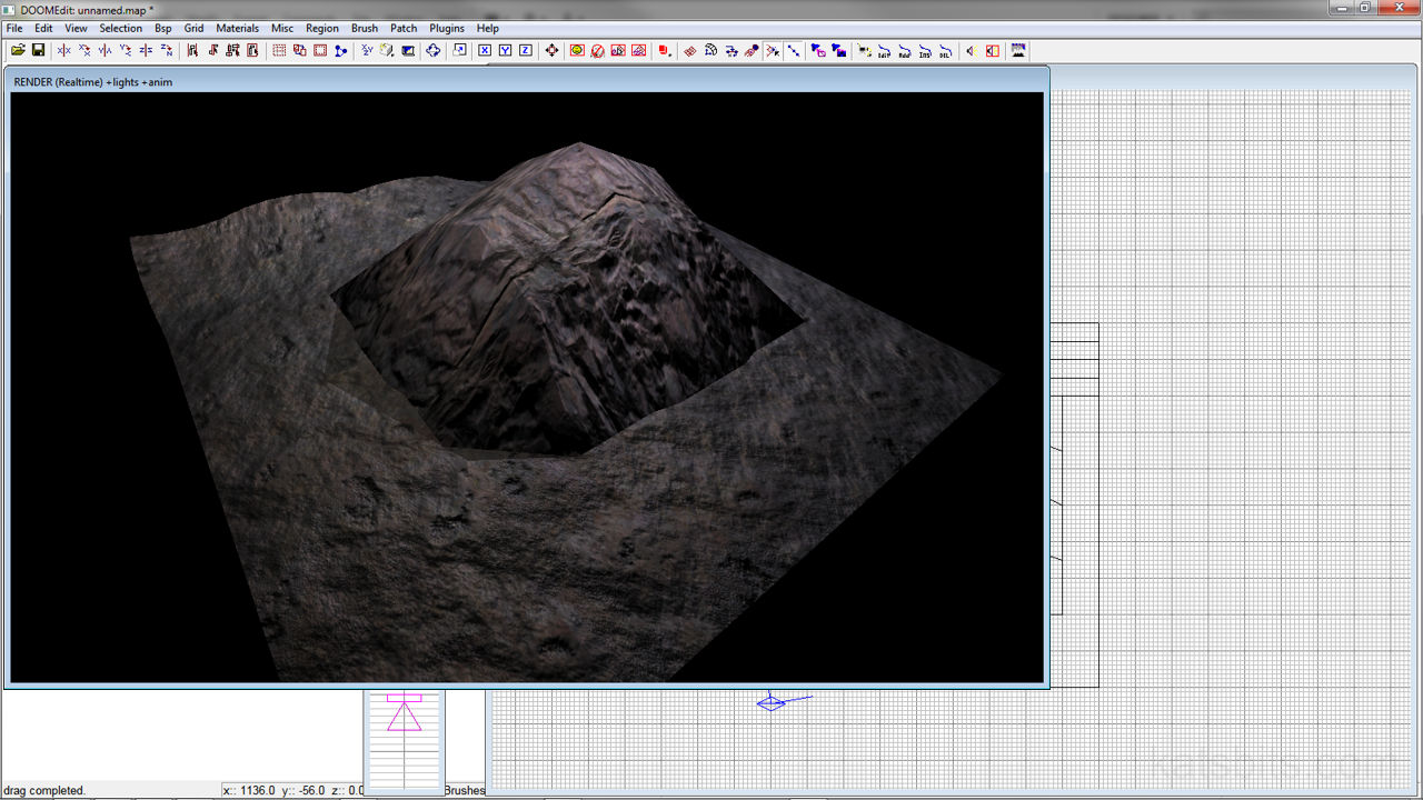
When rendered, the two mesh sections provide a relatively convincing terrain, albeit a bit simplistic when compared with a similar effort created in a modelling application like Blender 3D. Note that it’s not possible to ‘blend’ or ‘graduate’ the change from the ‘rock’ material to the ‘ground’
Patches & Vertex Texture Blending
As was mentioned briefly above, there is one one big disadvantage – well two really;
- You can’t texture blend – because you can’t vertex paint patch mesh objects (vertex painting is necessary for Doom 3’s texture blending system to work).
- You get ‘seams’ where sudden changes in texture type occur – as shown in the image above.
There’s nothing you can do about the 1st, but the 2nd can be dealt with by placing smaller objects around any ‘seams’; rocks, debris, walls etc., anything that breaks the appearance of the seams, basically by ‘hiding’ them. If it’s a real concern that the seams can be seen (and you’d rather not get you hands dirty in a modeling app) then what you could do is make a new texture in a photo editing app which blends together two textures. This can then be applied to another mesh and strategically placed over a seam giving the appearance of merging two or more objects together. Keep in mind that if you do this you’ll need to create new textures that also blend the local (normal), height and specular maps as well as creating a new material file.

