Basic Retopology (Retopo) in Blender 2.49
The follow written tutorial is a summary of the main steps using Blender 3D’s ‘retopo’ tool to rebuild a low poly mesh over the top of a high poly model. It’s assumed you know the basics of how to move around in Blender as well as some of the more common functions and features.
Retopo is short for ‘retopology’, the process of recreating a low poly model based on a much higher resolution object. This high poly object acts as a ‘template’ over which the low poly version is ‘redrawn’, giving at the end of the process, a second skin of sorts over the underlying model. The lower poly mesh can then be used for a number of things including the baking of the high poly to create normal maps UVW mapped to the retopo’d mesh, very useful for current generation normal mapped terrain’s that require greater visual depth without the expense of the huge triangle count usually associated with such detail.
IMPORTANT NOTE : the actual accuracy of the results are dependant on the user and not the tool itself; how you use retopo to redraw or describe the shape of the high poly mesh will determine the accuracy of the mesh – the more vertices (and hence faces) you create, the more accurate the mesh.
Snap Cursor to Object Centre
Before beginning it’s best to centre the cursor on the object that’s about to be Retopo’d. Select the high poly mesh that’s being used as a basis over which the retopo tool is to be ‘drawn’ and use the cursor snap menu to position the 3D cursor at the objects POO (Point Of Origin).
Design note: objects are placed into a scene based on where the 3D cursor is so it’s best to centre it so objects aren’t added too far away from the main mesh.
-
SHORTCUT KEYS
RMB to select object, "SHIFT+S" to bring up the "Snap" menu. Click "Cursor to Selection"

Once the object is selected and the cursor snapped to it, the Retopo process can begin
Add Plane Mesh (primitive) Object
For Retopo to work it needs an ’empty’ object, this isn’t the same as a proper ’empty’ (which is a helper/target marker), but instead a mesh object that contains no vertex or face data. To do this simply add a mesh ‘primitive’ to the scene… (cont. below)
-
SHORTCUT KEYS
Press "SPACE" to open up the "Add" menu, select "Add > Mesh > Plane"

Adding a ‘plane’ mesh object
Delete all Vertices
(cont. from above)… and then select all the objects mesh data (vertices, faces, etc.) and delete them. All that should remain is the objects POO (Point Of Origin). Depending on which edit select mode you’re in Vertices/Edges/Faces you can "Delete All" or the specific components you see, i.e."Delete Vertices" to remove all the vertices from the object (which will incidentally delete face data).
Design note: When adding a mesh Blender will place you automatically into edit mode, press "Tab" to toggle in and out of edit mode as you work when necessary.
-
SHORTCUT KEYS
Press "DEL" or "X" to bring up the delete menu, Click "Delete Vertices" ("…Edges/Faces/All")

Deleting vertices to leave a ‘clean’ POO behind before retopo can begin
Creating/Adding Vertexes (vertices)
At this point ‘retopology’ can begin by adding vertices along the contours of the higher poly object; in the "Mesh" panel click the button marked "Retopo" to turn on the tool and then begin by LMB clicking somewhere on the mesh to start the path (edge-loop), pressing "Ctrl+LMB" to add new vertices to the edge-loop chain.
As you work each vertex should ‘snap’ to the mesh directly under it, if it doesn’t appear to be doing this turning on ‘X-ray’ from the Object buttons window ("F7") should reveal where they are; due to the nature of retopo’ing lines of vertices may appear hidden from view because they don’t follow the greater profile of the high-poly mesh.
Design note: it’s useful here to turn off the mesh edit gizmo (the green, red and blue directional device used to show direction when working with selected objects) by clicking the little ‘hand’ icon in the 3D view-port header (has the word ‘Global’ next to it).
-
SHORTCUT KEYS
LMB click to begin initial vertex placement, additional vertices are added by "Ctrl+LMB". "F9" to view edit mode buttons, "F7" to view object mode buttons.
")
Laying down and adding vertices to a chain of vertices (edge-loop)
Creating Polygon Faces from Vertices
Once the initial set of edge-loops have been placed (a ‘top’ and ‘bottom’ set) it’s best to ‘fill’ them with a polygon; using fill allows you to see how the faces are sitting over the underlying high resolution mesh making it easier to see at a glance how the object is taking shape.
-
SHORTCUT KEYS
"Ctrl+TAB" to change edit mode selection to vertex/edge/face, click "Edge". RMB and "Shift+RMB" to select any two edges and then press "F" to ‘fill’ the selected whole with a quadratic or triangular polygon. Deselect ("A") and reselect two more and repeat the above until the polygons are placed how the should be.
Design note: it’s best to do this one face at a time so you can control the layout and orientation of the polygons as they follow the contours of the edge-loops (vertex chains).

The pink area above is a newly created polygon face after selecting two edges and pressing the ‘F’ key
Selecting a Vertex and Continuing
Once the first edge-loop is filled with faces the rest of the retopo’d mesh needs to be completed, simply select a vertex (usually along an edge somewhere) and hold the "Ctrl" key down whilst LMB clicking as before. Follow the contours and keep going until the whole mesh is covered.
-
SHORTCUT KEYS
Ctrl+TAB to change edit mode selection to vertex/edge/face, click "Edge". RMB and Shift+RMB to select any two edges and then press "F" to ‘fill’ the selected ‘hole’ with a quadratic or triangular polygon. Deselect ("A") and reselect two more and repeat the above until the polygons are placed how the should be.

Selecting a vertex along the edge of the low poly retopo work so the mesh can be continued
Final Retopo’d Mesh Surface
Covering the high resolution mesh with a retopo’d low version should result in a ‘skin’ approximating the shape and contours of the high poly If further tweaking is needed it’s just a simple matter of going back into the mesh (re-entering edit mode) and subdividing edges to create new vertices (and edge-loops) which can be manipulated to follow the underlying model more precisely
Design note: If/when the mesh needs to be further tweaked by creating new vertices it’s best to make sure the retopo is still on or turned on so the additional vertices snap and slide along the underlying mesh adhering to its shape as they are manipulated.
-
SHORTCUT KEYS
Select and edge or two or more vertices and click the "Subdivide" button in the "Mesh Tools" panel in edit buttons (F9)
")
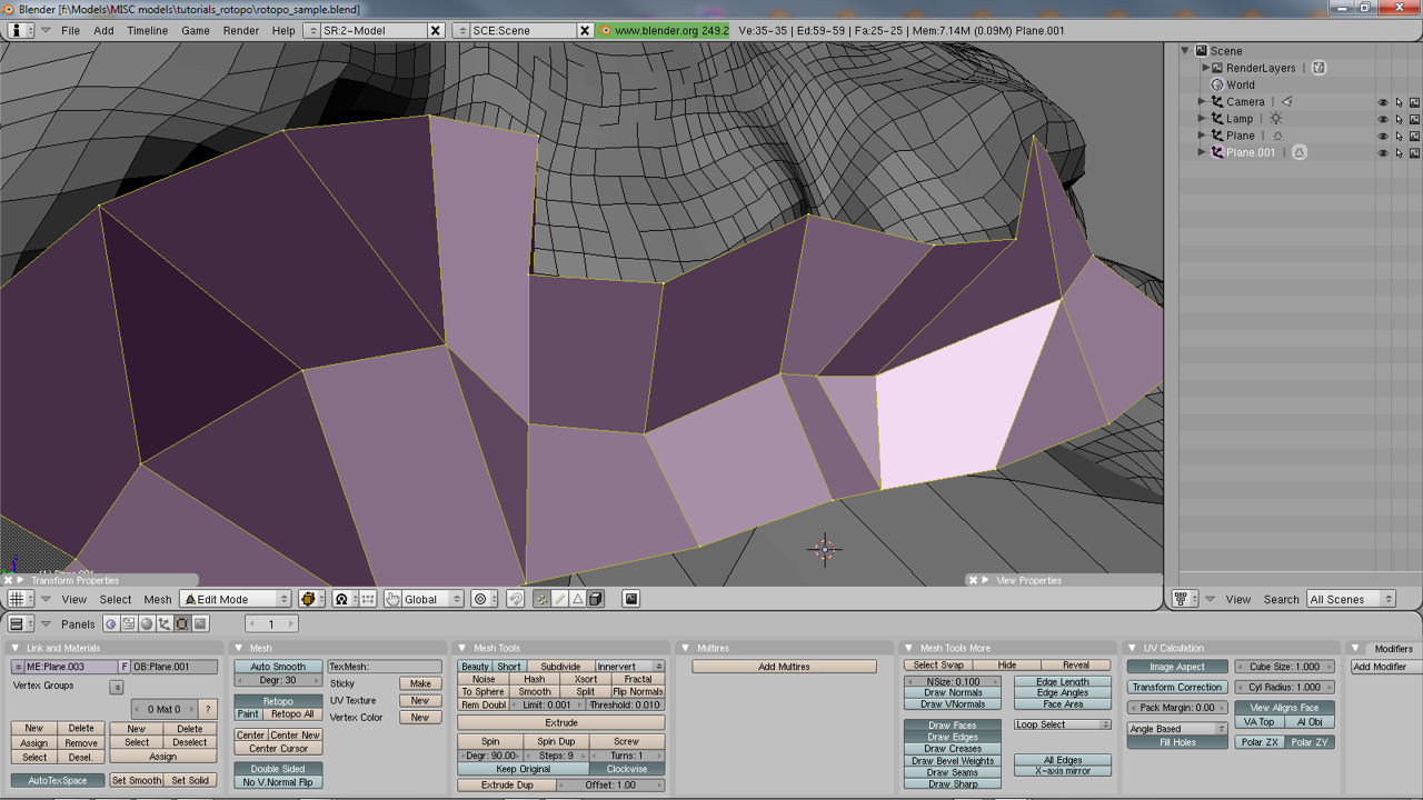
Low poly Retopo’d mesh in edit mode showing vertex chains (edge-loops)

In object mode with "Set Solid" active showing polygon
faceting

Set Smooth active
YouTube video of the retopo process (no audio)
Watch the video on using Blenders Retopo(logy) Tool

