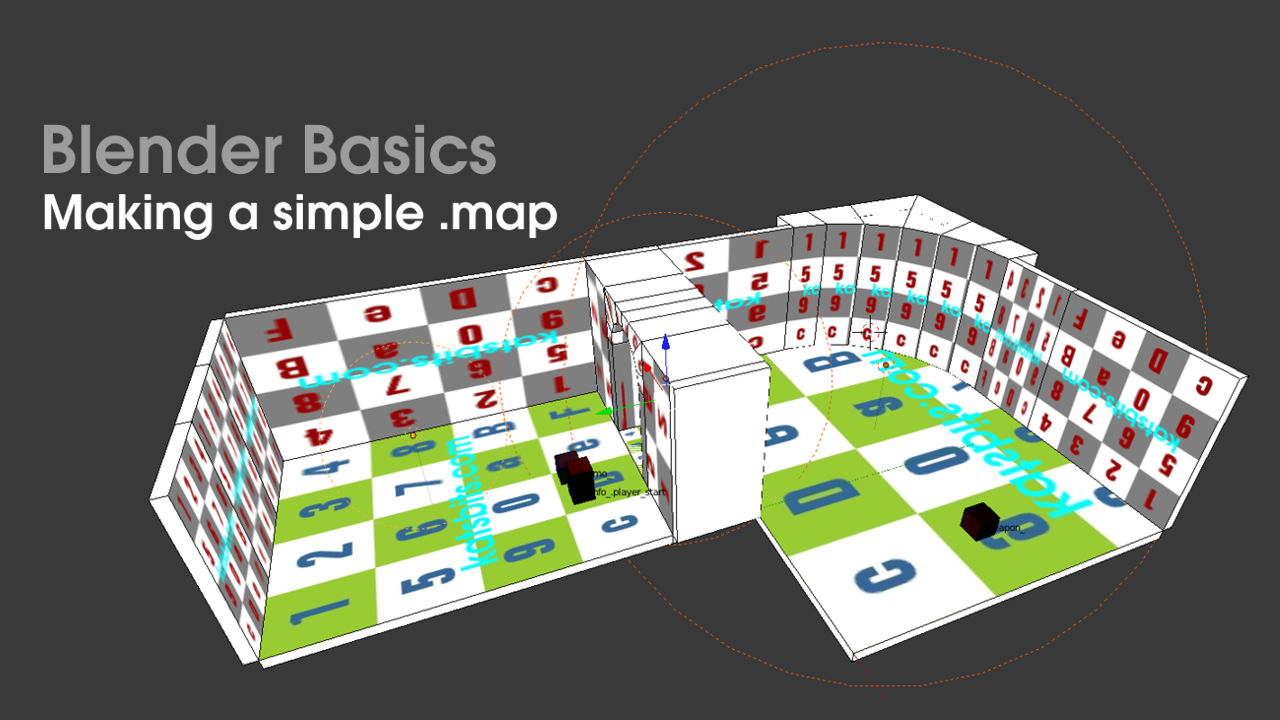
Map – Meshes (#2)
In the previous chapter we learnt the basic but essential information needed for .map based level design in Blender.
We discussed grid settings, matching the properties between Blender and level editor to ensure objects are the same size, shape etc.
We also learnt that because of the way the .map format works, we are better off making maps using simple blocks – primitive cubes and ‘regular’ shapes – because these types of object work best within the formats expectations. In this next section we’ll put this into practice and build a simple level.
Note that a basic understanding of Blender is required from here on in as we won’t discuss in any specific detail common actions like moving, navigating and manipulating objects which have been covered in previous tutorials here and here.
Download: KatsBits – Map Source (c. 10 MB | *.blend, *.map, *.obj, *.mtl, *.jpg,).
Resources
– Blender Entity Helper Kit
– Blender 2.49 .map making
– Quake III Manual
– GtkRadiant download
Prefabs, edge length & making a room
The easiest way to work with Blender within the context of .map based level design is to use “prefabs“. These are simple predetermined shapes, usually basic blocks or panels of set dimensions that can be duplicated, reused and/or resized to suit. As an example, shown below is one such prefab, a 128x16x256 ‘panel’ made by resizing the default scene cube in “Object” rather then “Edit” mode – the reason for resizing this way is simply that it’s often the most straightforward way to change the basic shape of a mesh when we’re not making complex forms, just RMB select the object and open the “View Properties” toolshelf panel (“N“), in the “Dimensions:” subsection change the “X“, “Y” and “Z” values to fit the shape required.

Resize the default cube to make an initial panel; based on the type of map to be made this will be the basic initial block from which others will be duplicated (but not linked) and resized and shaped as the map is built [see *.blend “1”]
If we do want to change a mesh in “Edit” mode, because we’re using objects of a ‘measured’ size, then ideally we need to change a few options so we know how big the mesh actually is (“Dimensions:” values are not displayed the same way in Edit mode). Select the mesh and “Tab” into Edit mode. First we need to turn on “Edge Length“. In the “View Properties” toolshelf (“N“) scroll down to the “Numerics:” subsection and activate “Edge Length“, a series of numbers should appear, if not select a face or edge to check – visibility is based on active selections. Next we need to switch to a “Global” display of measurement. Scroll back up to the “Median:” subsection and click “Global” – this changes the measurement system to use ‘global’ values so the numbers will change to represent their actual ‘physical’ or ‘real’ size relative to the scene rather than ‘local’ object sizing.

In order to see how big the mesh is in Edit mode turn on “Edge Length” – this displays selected element sizing information [see *.blend “1b”]

Using “Global” measurement values means the objects size will be displayed as it actually is rather than a ‘scaled’ value – the original cube has been scale up by various values so leaving “Local” active means we see size relative to ‘scale’
With the initial prefab made it can be duplicated using “Shift+D” (“Object » Duplicate Objects“) to create an ‘unlinked‘ copy of the original. This new object can then be resized to 512x16x256, creating another prefab that can be used for longer wall sections.
Design note: “Duplicate Objects” creates copies of an original item including its properties that can be edited independently or the original. “Duplicate Linked“, “Alt+D” – “Object > Duplicate Linked“, on the other hand keeps the properties and changes both the copy and original when either one is edited or altered. Note also that when moving or manipulating objects we need to press and hold “Ctrl” to ensure proper grid snapping in Blender.

Use “Shift+D” to make an “Unlinked Duplicate” of the first object and resize it using the “XYZ” settings of the objects “Dimension” properties to form the longer section of a wall [see *.blend “2”]

Or alternatively reshape the blocks in edit mode by manipulating the mesh as would be done for any object. Hold “Ctrl” whilst doing so to ensure grid snapping when using the widgets arms (RGB arrows)
Duplicating objects & finishing the room
Duplicate the prefabs previously made and position them to make the basic ‘block out’ of a room that’s 256 units high, 512 units long and 384 units wide along the inside faces (shown below), i.e. use two of the longer ‘512’ unit blocks for the walls on either side, three of the original ‘128’ unit blocks to form the front and back walls, and allow a gap for a passage at one end (delete one of the 128 units), we’ll be making use of this later. This forms the basic structure of the room, the ‘walls‘, in much the same as would be done in a level editor, it’s this single principle that is key to using Blender for .map based design because it replicates what we would otherwise be doing in said tools.
Design note: remember that whenever objects are moved and/or rotated in Object mode, and/or resized in Edit mode, to hold down the “Ctrl” so any action is properly snapped to the grid – this ensure correct alignment of brushwork when the eventual scene is exported out as a .map.

Duplicating objects to make the remaining walls. Note the back wall is made using the first block three times, this can be joined at a later stage it needed [see *.blend “3”]
‘Cap’ this initial block-out top and bottom by duplicating and resizing the original prefab (or other mesh) to create ‘floor‘ and ‘ceiling‘ units that are both 16x384x512 height, width, length (shown below). This completes ‘room 1’.
Design note: we’re defining the room based on the relationships between blocks. This means as we place each object next to it’s neighbour we create either “negative” or “positive” space – “inside” or “outside“. As the active area of the room is defined by a ‘negative’ relationship in this instance, that means the inward facing surfaces of each object is important in creating the ‘room’ itself.

Make a floor and ceiling unit by duplicating and resizing to fit the space, make sure only the inward facing edge is matched to the wall top and bottom (it’s not absolutely necessary or required to overlap the floor and ceiling blocks) [see *.blend “4”]
Pivot points, mirroring & layers
With the first room built we’ll use it to make a second room through its duplication and mirroring around a fixed point. We’ll then shift this new material to another layer to help manage the project better. First we need to fix a point around which the duplicated objects will be mirrored. To do this, press “.” (‘full stop’/’period’) or from the header menu click the “Pivot Point” icon and select “3D Cursor” (shown below), this will cause the “3D Widget” (the object with RGB directional arrows) to change its position to where-ever the 3D Cursor is located in the scene.
Design note: the default pivot is “Median Point“.

Before duplicating the object to make the new room set the “Pivot Point“, the location around which any subsequent action is orientated, by pressing “.” (period/full stop)
We now need to make sure the cursor is placed correctly relative to what we’re about to use it for; pivoting some objects around it. In the “View Properties” panel (“N“), find the “3D Cursor Location:” subsection and change each of the “X“, “Y“, and “Z” values to “0.0000“, this ensures the cursor is located dead-centre of the grid (and of the objects as we’re working on them).

Press “.” or set the “Pivot Point” from the menu selection forcing the widget to reposition itself relative to the cursors location which should be set using the “3D Cursor Location:” settings – be sure to use only whole numbers [see *.blend “5”]
Next, using an ‘either/or’ combination of “Shift+RMB“, “B” to border select or “A” to select everything in the scene, press “Shift+D” to make an unlinked duplication of the group. RMB click to ‘release’ the new objects, and whilst they are still selected use “Ctrl+M” to initiate “Mirror“, pressing “Y” to set the axis around which this should be done (“Object » Mirror » Y Global“), this will flip the entire section to the opposite side of the cursor. LMB click to set the action.
Design note: the actual axis used may vary depending on the orientation of the original room – if it was originally built using a “Front” perspective the axis will be different to said-same being built from a “Right” (or “Side“) point of view so be sure to use the correct axis, “X” or “Y” relative to the originals orientation.

Duplicate (“Shift+D“) the previously made room and mirror it (“Ctrl+M“) along the “Y” axis to create the new room
Once mirrored move the entire section to a new “Layer” by pressing “M” to open the “Move to Layer” menu. Click one of the buttons (button two, top-left is shown being used below). The meshes will disappear from view and be placed in the chosen layer which can then be viewed independently by clicking the appropriate “Layers” button/s in the menu header, or as part of a group by holding “Shift” whilst clicking various layers to de/activate them.

Use “Move to Layer” (“M“) to place new objects into another layer for easier management of the meshes and project [see *.blend “6”]
Reusing objects & finishing the second room
Because .map based levels are constructed largely from blocks, it means we’re actually defining architectural structures through the relationship between objects in a scene rather than the creation of individually complex shapes. For the most part then, the design process is simply one of changing the locations and/or positions of objects relative to their neighbours. We’ll use this principle to make room 2 ‘bigger’.
Activate the layer housing the objects we just made by clicking the associated layer button in the “Layers” menu, then holding “Ctrl” to snap actions to the grid, RMB click select and move one of the longer walls approximately 256 units away to one side. Duplicate or reuse one of the back wall segments and alter it’s size so that it fills the gap – the gap itself is “256” units wide so the duplicate will need to be changed so it too is “256” units in width. Alternatively, edit one of the meshes along the back wall, it should be approximately “384” units wide (its original “128” width plus the additional “256” of the gap).

Move the outer wall to one side and fill the resulting gap with a new object that’s either a resized duplicate of another section or edit one of the current back wall sections to fit the gap [see *.blend “7”]
Similarly, resize both the ceiling and floor meshes by changing the ‘object’ size or manipulating the meshes in Edit mode so the gap between old and new is also closed (shown below). They should be approximately “640” units wide, their original ‘length’ (“512” units) remains untouched.
Design note: changing the size of something in “Object” mode will often mean having to move or reposition items as the resize is based on the location of the objects “Point of Origin” (the small sphere often seen when selecting objects).

When editing meshes the origin point stays in it’s original location, so long as it and the mesh stay locked to the grid this shouldn’t cause too many issues [see *.blend “8”]
Then finally, along the ‘front’ end of the room (where the hole for the passage is) the gap created by moving the outer wall can be filled by moving and/or resizing one of the blocks previous located on either side of the doorway/passage opening. This will also be “256” units in width.
Design note: remember that resizing or reshaping objects can be done by simply changing “Dimensions:” data in “View Properties” or by physically altering the mesh in Edit mode.

Reusing a mesh object that’s no longer needed, putting it to use elsewhere and filling the gap along the ‘front’ wall [see *.blend “9”]
With these changes to room two done we’ve completed blocking out using the relatively quick and simple process of reusing previously made objects (prefabs).

Room 1. Note “Wire’ is active so individual brushes can be seen properly where more than one is used as part of the same area [see *.blend “10”]

Room 2. “Wire” mode also enabled for the same reason mentioned above [see *.blend “11”]
Adding a corridor between rooms
Next we’re going to add a corridor between the two rooms. To make this easier to do it’s best to use layers so we can properly focus on each group of objects in turn without over-selecting. First we need to move the rooms a short distance apart to allow placement of the corridor. Press “numPad5” then “numPad7” to switch to “Top” orthogonal view then click the corresponding layer button for ‘room 1’ to isolate the contents. Select all (“A“) and move (“G“) everything so the inner face of the side with the opening sits on the blue grid axis marker (shown below). This minor adjustment makes sure that major structural features are (ideally) ‘grid snapped’ – because of the way this first room was built, whilst the initial prefab was centred on the grid, the resulting room isn’t and should be fixed. Use “Ctrl” to help ‘snap’ whilst doing this and where necessary “MMB+scroll” to zoom into the scene allowing for movement using smaller grid increments.
Design note: using MMB+scroll to zoom into or out from the 3D view increases or decreases the size of grid snapping relative to the view whilst keeping the actual grid properties set in the “View Properties” panel the same. Alternatively, press and hold “Ctrl+Shift+drag” to use ‘macro’ movement.
With the adjustment to ‘room 1’ done, repeat for ‘room 2’; switch to the corresponding layer, select everything and holding “Ctrl“, this time move the objects 128 units ‘down’ (as we’re looking at the scene from the ‘top’) from it’s current position – 128 units is effectively two major grid segments – making sure to keep it aligned so the opening between rooms are parallel to each other. To check, “Shift+LMB” select layers “1” and “2” so the contents of both can be seen and compared, it should be similar to the image below.

With both Layers active so both rooms can be seen at the same time, move room 2 away from room one a short distance (128 units in this instance). Move Room 1 slightly so the inner faces of the area are aligned to the major grid [see *.blend “12 & 13”]
With the rooms suitably positioned we can now add the short corridor. Because of the way the rooms were built we had what appeared to be a number of unnecessary meshes, we can put these to use now. Exit orthogonal view if still in it from previous, “numPad5“, and select one of the passage walls from ‘room 1’. Enter Edit mode (“Tab“) and holding “Ctrl” click the corresponding widget handle (green in this instance) to reshaped the mesh from it’s original 16x128x256 to 128x128x256 units in size, filling the gap between the rooms. Exit Edit mode. With this done on one side repeat the process for the opposite by again selecting one of the unused objects and reshaping it also to make a block that’s 128x128x256 units in size. Together each individual element now functions as a ‘wall’ that defines the end of each room and the those of the corridor.

Reusing and resizing one of the end blocks from room 1 to create the corridor, this will be done on both sides [see *.blend “14”]

Using separate objects for each side of the passage means using more items than is strictly necessary [see *.blend “11b”]

Excess can be reduced by using mesh blocks more efficiently so that one single item can perform several functions at any one time [see *.blend “11c”]
For the ceiling and floor units, use the final remaining object and resize to 128x128x16 units, then duplicate and reposition it as either the ‘ceiling’ or ‘floor’ unit depending on which was done first. Once all the blocks are in place this should leave us with something similar to the image below and the basic level done.

Reusing and resizing another of the unused blocks to create a unit that can be used for both the floor and ceiling (once duplicated) [see *.blend “15”]

The completed corridor made by reusing and resizing some of the unused elements created when making the initial rooms [see *.blend “16 & 18”]

The basic structure of the two room level finished ready for textures and feature details (architectural) [see *.blend “17”]
Providing we stick to the way the .map format works in terms of it using blocks and simple shapes, making a level is relatively straightforward and doesn’t require some of the normal complexities associated with making models, a project can be developed and basic shapes and architecture blocked out quite quickly. Next we’ll go on to learn how to add and use curves.

