What Are Smooth Groups & Mesh Smoothing, And Forcing It In Blender
The preservation of Smoothing when exporting meshes for use in games can be problematic because, although it can be set using various tools in Blender or other 3D applications, the feature itself still relies largely on its being retained during the export process and / or maintained within a given game development environment.
Download: Katsbits Forced Smoothing Example (c. 100 KB | *.blend).
As such there are instances when the data associated with the attribute are either lost or ignored. In such instances Smoothing has to be ‘forced’, that is, the mesh has to be physically "Split" into an appropriate array of surface groupings so as to approximate the general appearance of what would otherwise be assigned via tools and property options.
The following tutorial on exporting models with Mesh Smoothing intact from Blender will use a simple cube by way of demonstrating the basic process of assigning forced smoothing to a mesh within the context of idTech, although, it is important to point out here the problem is not exclusive to that particular engine technology.
Why Use Mesh Smoothing?
Mesh Smoothing is generally about surface illumination, how objects are lit and shaded with respect to a Scenes lighting. When Smoothing is not properly assigned, or simply not used, models typically appear incorrectly lit and shaded. Smoothing, or more correctly the ‘groupings’ or ‘hard edges’ that can be formed as part of the process, alleviates this problem and is a primary reason why it’s used.

An example of why mesh smoothing is used. The wheelbarrow model with partially assigned Smoothing; edges that should otherwise display as ‘hard’ – edges or surfaces typically indicative of man-made structures – appear ‘soft’ and relatively indistinct which results in incorrect object shading

Once Smoothing, i.e. ‘groups’ and/or ‘hard edges’, has been assigned, surfaces shade correctly with respect to the way they would be expected based on scenes general illumination and light direction (top-left in this instance). This is the general purpose behind the use of "Smooth Shading", or "Mesh Smoothing" as it’s otherwise referred; to facilitate proper object illumination
Smoothing & Model Formats
Most model formats used for games are capable of utilising smoothing, so using idTech 4 as an example target technology, it comes as no surprise the three main model formats are similarly capable of displaying smoothed meshes. They are;
- *.ase: an ascii text based format native to 3D Studio Max.
- *.lwo: a binary compiled format native to NewTeks LightWave.
- *.md5mesh: a proprietary text based format developed for idTech 4 by id Software.
Each format can use Smoothing in one of two ways; 1) assigned to the mesh during construction and saved-to-file on export – how this is done varies depending on the 3D application being used, Smoothing can be a property such as "hard" or "soft" edges, or a physical effect such as "splitting" sub-elements, or creating "groups" of elements; 2) smoothing data from export is ignored in favour of game engine assigned properties, typically though a shader or material, or a generalised global value. For example the former is typical when working with *.ase or *.lwo models, the latter for *.md5mesh.
Design note: where *.md5mesh is concerned, global Smoothing assignments are used to compensate for seams (the hard edges associated with Smoothing and Smooth Groups generally) which can cause problems for normal mapped textures.
Mesh Smoothing & Splitting Surfaces
In instances where the export of Smoothing fails, or for whatever reason is not being used, the only way to generally guaranty inclusion is to force their placement. This is done by manually breaking up a models surface continuity into a series distinct areas or ‘groups’ through a process of face, edge and/or vertex ‘splitting’.
Design note: when talking about "Smoothing" and the use of "Smooth Groups" in this context, the latter generally refers to the overall affect of individual collections of faces, edges or vertices – the way a mesh splits indicates a ‘group’ (gives the appearance of), a collection of such can be referred to as a collection of "Smooth Groups". This should not be confused with the "Smooth Group" mechanism used in 3D Studio Max – although it works using the same guiding principle of surface ‘units’ (a ‘unit’ being a face or collection of faces), the underlying mechanism through which this is achieved differs from simple ‘splits’. It’s important to understand the difference and distinction between the two references.

Mesh Smoothing in a broader sense is typically composed of ‘groups’, or "Smooth Groups", individualised areas or regions that make up the whole aspect. Not to be confused with the proprietary system of managing, setting and controlling the same thing used by 3D Studio Max
The following will demonstrate this approach on a simple cube Object which has a single face selected and then slit from its neighbours resulting in two distinct groupings; the split face itself and the remaining surfaces of the cube.
Design note: "Split" is not the same as "Separate" (or "Detach" as it might be otherwise known) in Blender, the former simply breaks surface continuity, the latter into a completely independent object that’s neither attached nor connected to its originating parent Object in any way. Think of a box. The box itself is the parent object, it’s what the object is, a "box" comprised of a number of sub-elements, each is distinct in its own right, the "left", "top", "bottom", "right", "front" and "back". Whilst remaining part of the box itself they are "sub-elements", when detached from the box (cut away with a craft-knife), although they still contribute to the overall ‘shape’ or volume of the box, they do so now as separate "sub-objects", not "sub-elements". When using other 3D applications the same principle applies, faces and areas can be similarly separated. Note also that the idea here is to create the impression of distinct areas without necessarily doing that – groupings can become complex if Smoothing is ‘shared’ (one group ‘bleeds’ into another because they have a common surface for example) so areas may not need to be fully split.

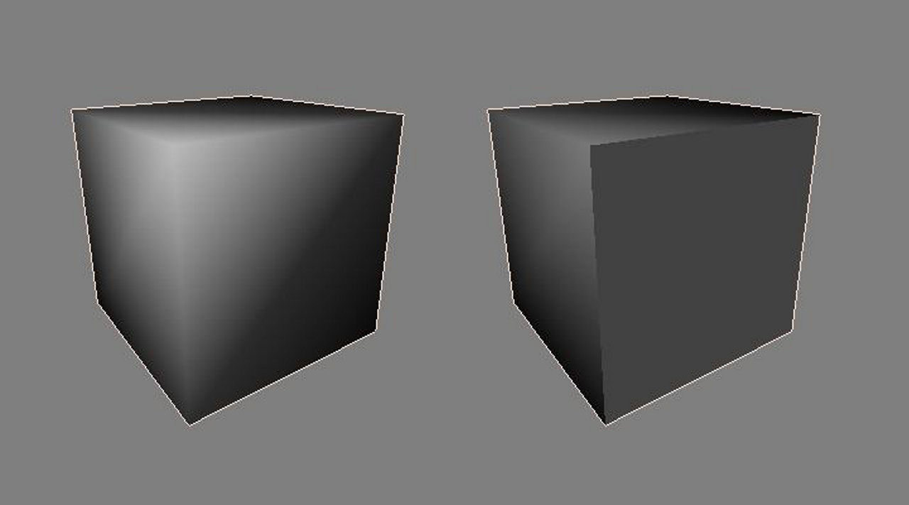
The general difference between surfaces "Split" (left) versus "Separate" (right) in Blender (separate is also synonymous with “Detach” in other applications
Manual Mesh Smoothing
To start with ensure smoothing has been enabled or assigned to the mesh. In Blender this is done by first selecting the Object ("RMB") and then in the "Shading:" subsection of the ToolShelf (the right hand side of the screen – press "T" if not visible), clicking "Smooth". The object will then display in the 3DView similar to the image below and as per the points previously discussed, shading is in the wrong place; because scene lighting is from top-right the bottom leading edge is incorrectly shaded – this is what Smoothing will fix.
Design note: shading issues can generally be fixed by Smoothing irrespective as to how it applied to an Object.

A box with ‘global’ smooth grouping (current Blender versions)
In Edit mode ("Tab") a face or group of surfaces are selected ("RMB" or "Shift+RMB"); using the demonstration cube "RMB" the front face this is the active select that will be split. Press "Y" or from the 3DView Header select "Mesh » Edges » Edge Split" ("Ctrl+E » Edge Split") or "Mesh » Vertices » Split" (or "Ctrl+V » Split"). This separates the selection at the element level (divides vertices or edges in to two separate but identically located elements) and changes the previously applied Smoothing by ‘breaking’ it at the point or points of splitting. Remember, this process is about ‘splitting’ edges (and associated vertices), it is not about detaching selections into completely independent objects.
Design note: note the basic principle being shown here, although done in Blender, is the same for all 3D applications where forced Smoothing is needed. Note also that although the integrity of the mesh should be kept whole (no gaps or wholes the break surface continuity), it may sometimes be easier to completely detach areas to better manage Smoothing assignments (which also might facilitate particular regions being worked on without the entire mesh being active in Edit mode). Once done however it’s important that all the separate objects be reattach (to use a 3DS Max term) them all back into one single object ("Shift+RMB" all the objects then press "Ctrl+J"). Because this usually doesn’t weld the vertices back together by default it will leave separated edges along the boundaries of what were separate objects before their being joined together.

Splitting the selected face away from other smooth groups
Split Faces, Edges or Vertices?
Although there are a number of menu options available to split a selection they all perform the same function, they split the mesh at the ‘vertex’ level. Shown below is what this generally means. On a simple object like the demonstration cube, splitting the selected face creates a set of coincidental vertexes, one for the selected element, the other belonging to the remaining surfaces. So two sets of vertices occupying exactly the same location belonging to different ‘groups’, and generally speaking this is how Smoothing works in game irrespective as to the technique used to assign them; vertices bordering split selections are ‘duplicated’ relative to the number of groupings required.
Design note: although not expressly discussed in this tutorial, Smoothing, that is the treatment of an objects surface to indicate distinct areas, can be carried out in a number of ways depending on the application being used to make the model. They all however, end up as split vertices at render time in game.

One of the vertex pair – belonging to the box – used to ‘force’ a smooth group split

The other vertex – belonging to the separated face – forming the corner pair
Smooth Groups Are Just Separated Vertices
The final result of the procedure is shown below, two ‘groups’ of smoothing – the main cube and the selected surface separated from it. When this mesh is exported, providing the vertices are not re-welded back together, the result in-game will be a replication of what’s seen in Blender.
Design note: export formats may inadvertently re-weld vertices back together as an automated ‘Remove Doubles’ of sorts so it’s best to do some basic tests to check to see if this occurs. Also, and irrespective, the same holds true with respect to game engines, some may persist in ignoring manually forced face splits similarly re-welding everything back together and assigning a single smoothing value.

The final ‘forced’ smooth group
Conclusion
For most low-poly work, the one caveat to this approach is that it creates hard lines where-ever surface continuity is broken (typically borders around groups). The only way to avoid, or at the very least mitigate this, and still keep a reasonable semblance of ‘smoothing’, is to "Bevel" ("Ctrl+B", "Ctrl+E » Bevel" or "Ctrl+V » Bevel") or otherwise ’round’ an edge by adding extra face or edge loops to redistribute shading across more surfaces, thus keeping the general forms present without necessitating the use or placement of hard edge between areas.

Adding extra loops around a group goes some way to alleviating the hard edges attributed to surface splitting but on complex models can be problematic to implement – smoothed (left), split (right), extra loops (middle), note that both loops and split version are similarly shaded
Care also needs to be taken with respect to animated objects. When splitting vertices it is possible to inadvertently alter vertex group values such that when the object articulates when animated, vertices attached to different ‘groups’ may move at different rates – be sure to double and triple check vertex groups, bone weights and modifier influences across coincidental vertices for disparities and synchronisation issues.

When faces are split to form smooth groups on animated objects care needs to be taken to ensure gaps don’t occur as a result of vertex group disparities

