Make A Column/Pillar From Patch Meshes In Radiant
This tutorial stemmed from a level built some time ago which required some curved ‘traditionally’ shaped columns. The way they were initially built just didn’t work; it resulted in far too many triangles being drawn by the game engine and consequently slowing down performance a great deal.
Patch mesh on the other hand are well optimised, with a gradual ‘LOD’ (level of detail) based on distance which helps performance issues a great deal. The following tutorial explains how to use Radiants patch mesh curve tools to create a pillar.
In The Beginning…
"… there was the ‘Radiant’, and it was a bright and shiny thing, the creator of worlds …."
Make sure you can see, or get access to the top, side, front and 3D camera views; either by setting up Radiant in ‘quad’ view (4 windows of equal size showing each orientation of the ‘world’. This is the default ‘state’ in which Radiant is installed and loaded), or by cycling the views in one main ‘grid’ viewport by using "Ctrl+TAB".
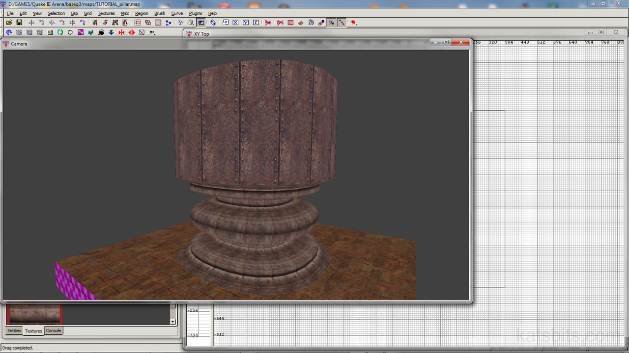
You’ll need the 3 main top, front and side views to edit the patches properly from all sides. The camera view will you the ‘3D’ progress as it’s being made. Just to give a basic visual grounding before starting, this tutorial will produce the finished result shown below – it’s a little over exaggerated so you can see the components that went into building it and obviously there’s no real need to make objects this complex if they’re not needed. Don’t worry it looks more complex then it actually is.
Design note: Keep in mind that this type of ‘modelling’ will skyrocket your r_speeds (poly count) if you do too much of it in one location, especially if you make the columns quite complex.

This is what we should end up with
As you can see in the picture above, there are a number of ‘basic’ shapes; the convex curves used to make the bulbous midriff; some flat sections creating ‘steps’ on the base section, and ‘fillets’ providing a smooth transition between the various shapes.
It’s worth pointing out here that in this example each section of the object is a separate patch mesh, the pillars foot for example is composed of the 3 sections;
- The ‘foot’ (the bit that sits directly on the ground).
- A ‘step’ (an upright surface decoration).
- The step top (the curved section that connects the ‘foot’ with the midriff).
The reason for using patch mesh cylinders in this way to build the pillar is to create ‘hard’ edges which result in a much ‘cleaner’ profile. If you wanted a ‘softer’ profile, using fewer meshes would do this. The image below demonstrates this by showing the two main ways to create a ‘curve’ depending on the result you were trying to achieve;

Different approaches to the use of patches will result in shapes that have a pronounced roundness or angular
Design note: although patch meshes like this has LoD (Level of Detail) attached to it – basically, fewer polygons are drawn the further away you are from the object – using more then one patch will mean more polygons are drawn by the game engine, possibly having a ‘negative’ effect on performance, esp. on lower spec’d machines.
You’ll notice if we use one single patch and shape it you end up with quite an ‘sharp’ curve; the advantage of this method is primarily to do with fewer polygons being drawn the game engine. If we use two or more to create a more rounded, smoother shape, it looks better but at the cost of rendered polygons in the game, it’s rendering twice as many. It does however, have the advantage of allowing you to use two different textures, one of each side.
Keep this in mind when you design your levels architecture.
Making An Object Using A Single Mesh
Our ‘building block’ for this tutorial is the cylinder patch (shown below). You need to be in ‘top view’ for this to make sure that a standing pillar is the right way up; doing this simply saves having to rotate the mesh because Radiant will create the cylinder in such a way as you’re always looking through it’s centre. Toggle your grid viewport using "Ctrl+TAB" until you’re looking at the top view.

Our basic building block – a cylinder patch mash
Draw a ‘brush’ object in the normal way ("LMB+drag") make it roughly the size of the cylinder shown above. Leave it selected (making sure you are looking at the top of the mesh) convert it to a cylinder patch mesh; "menu: curve » cylinder"; you should have an object similar to the above.
Once we’ve got this mesh the next stage is to ‘vertex edit‘ this patch mesh object – you can see in the picture above there are some small coloured squares at the extreme edges of the mash, these are ‘control vertices‘ that allow the manipulation of the object, changing it’s shapes and relative size.
Vertex Editing (Manipulation)
As mentioned above, once we have a mesh the next stage is to change it’s shape; to do this we need to be in ‘Vertex edit’ mode. Pressing the "V" key whilst an object (brush or patch) is selected will toggle you in to and out of vertex mode. This principle of vertex editing (or using the ‘control vertices’) is used for all patch mesh objects; cylinders, flat meshes, bevel etc.
The image below shows part of the pillar mesh in vertex edit mode with one side of the middle section already manipulated and pulled outwards (so it creates the midriff bulge). The blue squares show the currently selected set of vertexes; pink and green are unselected.

Editing the vertexes on the patch mesh
Design note: it may take you several attempts to select all the vertexes on a ‘row’ because of the different selection methods the editor uses; (LMB) single click, single click + hold. If you LMB click and move a selected vertex you may find you’ve left some in their old position, don’t worry about this, just LMB select the ‘old’ vertexes and move them to the new position.
Go to your side (or front) elevation/window and select the middle set of vertexes ("LMB+hold"). Using the view you’re in drag the set of vertexes outwards as shown above (by 64 grid units). Press "Esc" (or "V") to deselect the vertexes. Apply the same manipulation to the vertexes on the other side of the mesh. Once you’ve done this, move to your front (or side) elevation/window and apply the same changes to the mesh vertices in that view.
What you should end up with, is this (pictured below)

The finished result of manipulating a single patch from it’s central vertexes
You can make the convex (bulge) curve more pronounced by pulling the middle row of vertices out further; doing this will give you a very angular looking curve; or by pushing them back to the point of origin for a shallower curve.
Design note: you can get a ‘concave’ curve (inward facing curve) by either pushing the centre vertices further in, or pulling the top and bottom set out.
If you want to change the size of the patch globally it’s easiest to do this in ‘normal’ editing mode, press V to (exit vertex mode and) enter normal mode, just resize the patch the same way you would do with any brush/patch ("LMB+hold") (near an outside edge) and drag and then go back into vertex edit mode when you’re done.
[1: Patch Mesh Basics | 2: Multiple Meshes | 3: Advanced Patches | 4: Pillar Support]

