Gingerbread – Rigging (#3)
In Part III of “Make a simple animated Gingerbread character in Blender“, with the construction of the mesh complete, materials, textures and UV maps applied, it can now be ‘rigged’ and readied for animation. Before doing so it needs to undergo some basic preparation, largely to avoid issues later in the process, before then being linked to a skeleton and set up so it articulates properly during animation.
rigging
Many of the problems that occur during these latter stages of the process, that is rigging and animating a mesh, can be traced back to omitting one or more of the following;
- Not properly locating the model on the grid.
- Forgetting to reset the ‘mesh data’.
- Incorrectly positioning ‘origin’ points.
They’re important points to be aware of before actually rigging characters or building the respective underlying skeleton used to articulate the mesh because their ‘aspects’, what they are, is used crucially to determine the location of the mesh and how the rig and subsequent animation data relate to it. In other words, they help define the physical coordinates of the various components that go into making, rigging and animating an object. This is vital for content used outside the Blender environment because problems that do occur usually happen not so much because of what Blender does, rather because other tools and applications are not Blender so don’t understand ‘local’ context.
Design note: Blender understands the ‘global‘ position of an object relative to the Scene, whereas third-party applications don’t, which typically use ‘local‘ attributes rooted relative to the mesh itself.
With that said the process of ‘rigging’ the Gingerbread character, i.e. preparing and setting it up for animation, is relatively straightforward; aside from the aforementioned, the mesh is given a rudimentary skeletal structure, an “Armature“, comprising a series of individual “Bone” units that represent, and correspond to, particular sections of the mesh. Both mesh and bone are ‘linked’ together through the use of named “Vertex Groups“. The skeleton is then further optionally enhanced using “Inverse Kinematics” that aid the deformation and articulation of both mesh and Armature.

The mesh after Materials, Textures and UV unwrapping has been done, ready for the next step in the process; preparing the mesh and rigging for animation -the mesh is displayed in “Texture” mode, “Alt+Z” with the default “Lamp” removed to make it easier to see what’s going on (to another layer in this instance)[“uvmapped.blend“]
Preparing the mesh for Rigging
The first thing to sort out before rigging is to adjust the baseline of the mesh so it sits correctly on the horizontal ground plain (the “X/Y” axis); by virtue of the character being built from the default Scene cube this is currently its centre-of-mass prior to editing so the ground plain current cuts through the middle of the mesh. This needs to be changed so the characters final position has it appearing to walk on the ground rather than be embedded in it (at least to the degree it is at present).
To do this, switch to “Front” Orthogonal view (“NumPad 1” then “NumPad 5” or vice versa) and “Tab” in to Edit Mode. Select the entire mesh, “A” (which may need to be used twice, once to deselect, then again to reselect), then “LMB+drag” the ‘blue‘ handle of the widget up, mesh moving along with it, until the ‘feet’ of the object are roughly parallel the ‘red‘ line marking the horizontal “X” axis. Release “LMB” to confirm. Alternatively press “G” then “Z” to free translate locked to the vertical axis, move the mesh up and “LMB” click to confirm. Switch the “Right” side view (“NumPad 3“) and similarly make any adjustments if needed so the ‘blue‘ vertical line indicating the “Z” axis passes directly down through the centre-of-mass of the mesh. Press “Tab” and exit Edit Mode.
Design note: it’s likely the background image is still visible at this point, as its no longer needed is can be turned off by deactivating the “Background Image” checkbox in the “Properties” panel of the 3D View – this will leave the data in place and accessible but just turn off the display of the image (press “N” to access, or select “View » Properties” from the Header menu). When positioning the object be mindful it should ideally embed a small amount in to the ground plain to indicate ‘standing weight’, i.e. that the object has some weight and is sinking into the ground as a result – this avoids having to otherwise do this using small movements in the animation. Additionally, because the character is not exactly symmetrical, the vertical axis, “Z“, may not be centre exactly on the mesh, in which case align it with the inverted “V” between the legs.

Making adjustments to the mesh so the bottom of the feet sit roughly on the ‘red’ horizontal baseline and the ‘blue’ vertical axis passes up through the centre of the mesh, both important for the rigging process and later animation [“rigged-repositioned.blend“]
Once the mesh is positioned, next to check is the objects “Origin“, the small orange dot that will be, again if the default Scene cube was used to build the Gingerbread character, sitting at ground level. This must be located at Blender’s grid centre, or the “X, Y, Z” coordinates of “0, 0, 0“. If not, it can be moved there manually using a specific target as a reference, in this instance the 3D Cursor.
Design note: it’s beyond the scope of this tutorial to go in to too much detail as to why it’s important to check the origin of a mesh (and other elements) suffice to say that, outside Blender the “Origin” point is used to determine the object’s location and dimensions in space relative to a fixed point; it’s not just about altering the mesh so it looks like it’s walking on the ground.
To do this first set the cursors location. If not visible press “N” to access “Properties“(or select “View » Properties” from the 3D Views Header) and scroll down to the “3D Cursor” subsection(click the ‘expand’ triangle if the options are not shown). Here in the “X:“, “Y:” and “Z:” input field respectively “LMB” click to edit and type or make sure the numbers are all zeroed out, i.e. “0.0000“. If the cursor is not already at that location it snap to those grid-centre coordinates. Next from the Tool Shelf on the left (press “T” if not visible) under “Tools“, click the “Set Origin” menu button and select “Origin to 3D Cursor” from the list. The mesh Origin will immediately relocate to the 3D Cursor (if not there already).
Design note: even if the Origin appears to be located at grid-centre it’s always a good idea to go through the process anyway to make absolutely sure it is.

Setting the “Origin” point of the mesh so it sits at grid centre or the “0,0,0” coordinates for each of the “X“, “Y” and “Z” axes – this is important so as to make sure the mesh is correctly positioned in relation to the Armature, animation and possible use outside the Blender environment [“rigged-origin-reset.blend“]
With the position of the mesh changed and the Origin point set, the final check to make before rigging is to ‘reset’ that “Object Data” attributes. What this does is fix the object itself relative to ‘scale’, ‘rotation’ and ‘location’ as a volume defined as a “Bounding Box“. It’s another aspect of preparation that’s important to address because an objects size can be multiples of a base value, which is meaningless out side Blender. Resetting ostensibly avoids this problem.
Design note: the difference between an objects ‘volume’ and it’s ‘structure’ is akin to a football (soccer ball) in a box; although the ball itself is round, the box containing it isn’t, being a slightly larger ‘volume’ than the objects actual ‘shape’. If the box is too big for the ball it can be said to be ‘x’ times larger, or ‘scaled’, than the ball. In other words if the ball and box were originally 13 unit and scaled up x3, the result is not an object that’s33, rather it’s13 unit scaled up by 3. The same holds true for ‘rotational’ and ‘positional’ information.
To fix this, with the mesh selected (“RMB“) in “Object Mode“, from the 3D View Header menu select “Object » Apply » Rotation & Scale“, or alternatively press “Ctrl+A” to access the “Apply” menu pop-up and select “Rotation & Scale” from the list.
Design note: fixing object data cannot be done in Edit Mode. The information attributed to the object can be seen in the 3D View’s “Properties” panel (“N“) or by accessing the extended “Object” data properties by clicking the Properties button displaying an orange cube to the right of Blender.
It’s likely nothing discernible will happen to the mesh but looking at the objects “Transform” data (either in the “Properties” panel or “Object” properties as mentioned above), the numbers attributed to it’s “Location:“, “Scale:” and “Dimensions:” may have changed; crucially for rigging, the “X:“, “Y:” and “Z:” values for “Scale:” should register as”1.000“. Once these basic preparation have been done the character is ready for rigging.
Design note: before continuing it’s important to note that resetting object data, origin and adjusting the position of the mesh can be problematic to adjust and/or fix once an object has been rigged and animated because of the way Blender interprets positional data – if a mesh contains ‘errors’ relating to the aforementioned, and they are subsequently corrected, mesh articulation and animation may become corrupt because ‘local’ coordinate data associated with the relative positions of bones or mesh vertices has been changed.

Mesh displaying its “Bounding Box” (in “Object” properties under the “Display” subsection, activate “Bounds” to see the box whilst in “Texture” display mode, else just select “Bounding Box” from the “Display Mode” selector), or ‘volume’ as it relates to “Object” data properties; “Scale:“, “Rotation:” and “Location:” [“rigged-object-data.blend“]
Rigging & building an Armature
Once the objects location data, Origin and physical position have been adjusted as needed, it’s time to start the rigging process by giving the Gingerbread character an underlying skeletal structure that can be used to articulate the mesh and create animated sequences. This is usually done using an “Armature” object to control the general location of the overall character, whilst individual “Bone” elements articulate corresponding sections of the mesh. First however, check the position of the “3D Cursor” in “Properties” (“N“) to make sure it’s located at “0, 0, 0” grid centre (“X: 0.0000“, “Y: 0.0000” and “Z: 0.0000“).
Design note: the Armature, like the mesh, is defined by the location of its origin, the two objects need to match else the disparity can cause positional issues for the objects themselves as well as any attributed animations.
To do this, if still in Edit Mode press “Tab” to exit back into Object Mode – the following cannot be done in Edit mode – and then from the Header menu select “Add » Armature » Single Bone“, or press “Shift+A” to access the “Add” menu similarly select “Armature » Single Bone“. An elongated triangular object will appear in the 3D View at the 3D Cursors location (cf. above and note below). This is an “Armature” object and the single bone visible the starting point for the necessary skeletal structure to be built that’s needed to articulate the mesh.
Design note: when adding new objects or items to the Scene they appear at the 3D Cursors location; the new Armature object needs to be located at grid-centre (matching the mesh) so if the Cursor is not at that location beforehand, position it as discussed above or alternatively, as the Armature needs to be placed at the mesh objects Origin, “RMB” select the mesh, press “Shift+S” to access the “Snap” menu pop-up then click “Cursor to Selected” to force the 3D Cursor to the mesh (or from the Header menu click “Object » Snap » Cursor to Selected“), and then similarly snap the new Armature object to the Cursor using “Object » Snap » Selection to Cursor“, or “Shift+S” selecting “Selection to Cursor“.

A single boned “Armature” object added to the Scene at the 3D Cursor’s location from which the character entire skeleton will be constructed – shown in “Wireframe” mode for clarity (press “Z” to toggle from “Solid” or “Texture“, “Alt+Z“) [“rigged-armature-add.blend“]
To modify the Armature, with it selected (“RMB“)press “Tab” to switch from “Object Mode” to “Edit Mode“. It’s appearance will update slightly in confirmation.
Design note: Armatures tend to be added to the Scene as ‘objects’ in “Object Mode“. This may depend on the version of Blender used however, as they sometimes appear pre-selected in “Edit Mode” – check the “Interaction Mode” selector in the 3D View’s Header to see which ‘mode’ is active. Alternatively check the location of the “Transform” widget; in ‘object’ mode its located at the Armatures Origin, in ‘edit’ mode it will be located based on the active element selected.
Next “RMB” click the main body of the bone to select it (the elongated section between the two spheres) and from the Header menu click “Armature » Duplicate“, or press “Shift+D“. A separate new bone will appear moving with the mouse. Press “Esc” or “RMB” to release it from mouse control then whilst still selected, “LMB+drag” the ‘blue’ arrow of the “Transform” widget (or press “G” then “Z” to move locked to the vertical axis) and position it so the lower sphere is approximately where the legs join the body (the inverted “V” between the legs). Release “LMB” to confirm (or if using “G“, “LMB” click confirm). This new bone is what all the others will be connected to, the arms, legs and remaining torso segments, with the original acting as a ‘root’ or ‘master’ that’s generally never used for animation, rather as an in-game positional reference point.
Design note: editing the structure of an Armature, i.e. how many limbs it might have for example, is much like mesh editing in that changes can only be done in the mode dedicated to that, “Edit Mode“.
With this second lower torso bone created “RMB” click the upper sphere, the “Tail“, and “LMB” click drag the ‘blue‘ handle of the “Transform” widget upwards to the ‘mid-point‘ of the mesh (approximately). Release “LMB” to confirm the new position. This resizes the bone.
Design note: alternatively press “G” to initiate “Translate“, “Z” to lock the axis (up/down), and similarly move the selected element up to the meshes mid-point. “LMB” click to confirm – when moving the selection holding down “Ctrl” snaps to the grid which helps with alignment wherever axis locking (pressing “X”, “Y” or “Z” after initiating an action) is not used. Additionally when bones are modified their overall proportions remain constant so bones will actually increase or decrease in size rather than distances between top and bottom changing.
Next with the “Tail” sphere is still selected, from Header menu select “Armature » Extrude“, or press “E“. Another new bone will appear this time attached to the previous. Press “Z“, again to lock the axis, then move the mouse and selected sphere upwards to the ‘neck‘ of the mesh(approximately) before then “LMB” clicking to confirm. This will be the ‘upper body’. Then finally repeat the once more, selecting and extruding the “Tail” sphere of the bone just extruded (should be selected by default) – “RMB” select the sphere, press “E” to extrude and then move the mouse upwards towards to top of the head before “LMB” clicking to confirm and set this last (for now) bone in place. This will be the ‘head’.
Design note: bones can be manipulated immediately or after being ‘released/reset’ using “RMB” click or pressing “Esc“; the difference tends to be just one of control, as the speed at which a bone moves is relative to the location of the mouse at creation – close to and the bone moves quickly, far away and motion is slower and more controllable (across shorter distances). Additionally to using “Z” to constrain the axis, pressing “Ctrl” whilst moving the mouse will engage grid snap.
The result of these initial steps is an Armature comprising four bones, in two sections; a lower section containing the original ‘root‘ bone named “Bone“; an upper section containing a chain of three further bones -a ‘lower torso‘, an ‘upper torso‘ and a ‘head‘ bone, each assigned an automatically generated but temporary name, appended an incremental numerical value making each unique, “Bone.001“, “Bone.002” and “Bone.003” respectively (cf. image below).
Design note: bones names are appended incremental numerical values to make them unique, this allows each to be assigned an individualised property, and for different relationships to be established between them where more complicated rigging might be needed.

So far the Armature contains four bones generated as duplicates or extrusions from others and essentially separated into two sections; the lower containing the original bone; an upper containing a chain of three for the ‘spine’ of the character – shown in “Wireframe” for clarity [“rigged-spine.blend“]
Once the spine has been built the legs and arm are next. Although they can be extruded, quick way to generate them is to duplicate a pre-existing selection.
Design note: the advantage of duplication over extrusion relates to the resulting unitnot being physically attached to the bones from which they are made. This is handy for Armature sections dealing with appendages as they’re not normally in close enough physical proximity to the spine for that type of connection to be meaningful.
To do this “Shift+RMB” select two linked bones from the upper section of the Armature and press “Shift+D” to “Duplicate“, or from the Header menu select “Armature » Duplicate“. A new two-bone chain will appear again automatically named (“Bone.[n]“). Whilst still active (responding to the mouse) move it to the right (the viewers right) side away from the spine section and “LMB” click to set temporarily in place. This unit will form the basis of both arms and legs units of the character.
Design note: the two new bones need to be “Connected” to each but not the spine section (to which they are just ‘linked’) this can be verified in the “Parent:” subsection of “Bone” Properties where “Connected” should be disabled (blank checkbox). There is an even quicker way to create bones but this results a chain of bones still connected directly to an originating bone (the bone used as their respective ‘spawn’ point reference) that then requires one or two additional steps to unlink and adjust. Whilst not too useful in this context, for more complex bone arrangements being able to place then with “Ctrl+LMB” is handy.
First however, the new unit needs to be flipped because the sphere at the end, or “Head“, of the lower bone is the point around which the chain should articulate, i.e. it will be the characters ‘shoulder’ pivot. With the two bones still selected, in the 3D View’s Header menu click the widget button corresponding to the “Rotate” manipulator and, if the Scene is still facing “Front” (“NumPad 1“), “LMB+drag” the green circular outline, rotating the unit until it’s inverted (hold “Ctrl” whilst doing this to grid snap, making alignment easier). Release “LMB” to confirm. Alternatively press “R” then “Y” to activate free “Rotate” locked to that axis, “LMB” click to confirm once inverted. Once the arm is correctly orientated press “Shift+D” whilst selected making another instance, move this down to the leg on the same (right) side as the arm. “LMB” to confirm and set in place. The result should be an arm and leg roughly placed respectively on one side of the Armature.
Design note: when looking at the transform widget the white outline that’s visible always indicates a rotation or manipulation relative to the screen; in “Front” (“NumPad 1“) Orthogonal view this means rotation occurs explicitly around the “Y” axis (which is facing the viewer). In perspective mode this principle can be seen more readily as each “X“, “Y” and “Z” axes appear, and can be manipulated, independent of the white outline. To manipulate a selection around a specific axis press one of “X“, “Y” or “Z” to lock to that orientation during manipulation.
With this done from the “Transform” buttons in the 3D View Header again, click the button illustrated with an arrow-headed to switch back to “Translate” and “RMB” select the “Head” sphere, now the very top of the upper bone. Then using the ‘red‘ (“X“) and ‘blue‘ (“Z“) axis markers,”LMB+drag” the selection to roughly where the characters shoulder should be; then the middle control point between the two bone to about two-thirds the way down where the ‘elbow’ should be; and the very bottom sphere to align with the bottom of the hand/fingers of the mesh. Using the widget “LMB” release after each action to confirm their respective new positions. When placed correctly the result should be a slight ‘kink’ or bend in the middle of the bone chain corresponding to an ‘elbow’ or natural ‘bend’ in the arm (shown below).
Design note: alternatively with “Head” or “Tail” control sphere selected press “G” to ‘free translate’ so they can be moved across more than one axis at a time, “LMB” clicking to confirm once positioned – using free-translate tends to work better in Orthogonal rather than Perspective else manipulations will need to be restricted to an axis pressing any one of “X“, “Y” or “Z” keys after “G“.
Similarly with the ‘leg’ unit, “RMB” select the upper “Head” sphere and using the “Translate” widget, or pressing “G” to free-translate, reposition it roughly inline with the bottom of the spine (bone), but in the middle of the leg (mesh). This it the hip, the top of which is the rotational pivot for the entire leg. Then as with the arm “RMB” select the middle sphere of the two leg bones, position it at the ‘knee’, and the lower sphere at the base of the foot, “LMB” clicking to after each edit to confirm.
Design note: as with the sphere end of the arm, due to their respective shape the end of the lower leg bone may protrude below the mesh without issue. Additionally, note that with the character being relatively ‘flat’, it’s a biscuit, there is no real need to check the position of the “Head” and “Tail” control points relative to “Right” (“NumPad 3“) and “Top” (“NumPad 7“) views – ordinarily a character might have a slight kink or bend to the mesh at the elbow or knee so bone positions typically need to be reflective of this across all axes, for something like the Gingerbread character this isn’t strictly necessary.
Then finally, because the arm and leg were random duplicates of previously existing bones their respective “Parent » Child” relationship is likely incorrect – the ‘upper arm’ should be parented to the ‘upper torso’ bone, with the ‘upper leg’ parented to the ‘lower torso’. To fix this click “RMB” select the ‘upper arm’ bone and from “Bone” Properties (click the button on the right illustrated with a ‘bone’ icon) check the “Parent:” attribute in “Relations” – the name listed should correspond to the bones current name, i.e.”Bone.002” as the parent for the arm (“Parent: Bone.002“). If the names appear incorrect “LMB” click the input field (with the bone icon to the left) and from the ‘bone list’ that appears select the correct entry. The thin dashed line indicating the relationship between bones will adjust accordingly. Repeat for the ‘upper leg’, similarly checking or selecting the correct reference, “Bone.001” from the list to set its parent where necessary (“Parent: Bone.001“).
Design note: the thin dashed line is a visual indicator of the relationship between bones from “Parent” to “Child” or “Tail” to “Head“, as this changes so too does the line (the line always changes but bone positions may not depending on the connection between them).
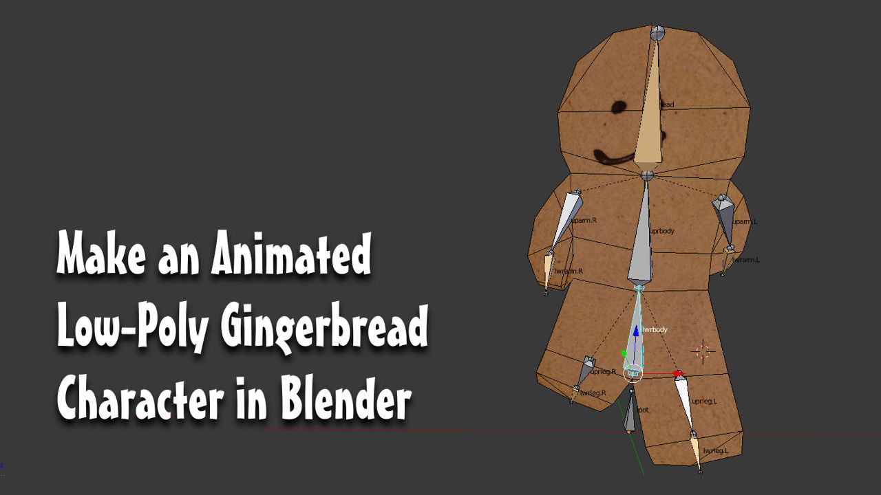
At this point the Armature should now comprise four sections; ‘root’ (x1 bone), ‘spine’ (x3 bones), ‘arm’ (x2 bones) and ‘leg’ (x2 bones),each sequentially named “Bone.[n]” (where [n] is a numerical value). The final step is to complete the skeleton so it has both a left and right side. This is done through ‘mirroring’.

Shown in “Wireframe” for clarity, the Armature with one half of the rig done – note at this point bone names are automatically generated and have no context so changing bone relationships where needed may involve a minor amount of trail and error selecting the correct bone from the “Bone” properties list. If bone names are not visible select “Names” from “Object Data” Properties[“rigged-left-side.blend“]
There are a number of ways to ‘mirror’ an Armature so both left and right are exactly the same, the most straightforward is to duplicate one side and flip it across a fixed axis or pivot point, in this instance the “3D Cursor“. To do this, first check the 3D Cursors location to make sure it’s at grid-centre “0,0,0“, also the centre of the character. From the “3D Cursor” subsection of “View » Properties” (“N“) check its “Location: “to make sure each “X:“, “Y:” and “Z:” coordinate is set to “0.000“, i.e. “X: 0.0000” (“LMB” click each input field as needed and edit the values if not). Next from the 3D View Header click the “Pivot center for rotation/scaling” button to the right of “Display Mode“, illustrated with a ‘target’ like icon, and select “3D Cursor” from the list, or alternatively press “.” (full-stop/period). The manipulator widget will jump to the cursor indicating its pivot point has changed.
Design note: the default ‘pivot’ mode is “Median Point“, scaling, rotation etc. is based on an averaged centre-point based on all the objects selected. Shortcut is “,” (comma). If the widget is already at the cursor nothing will appear to happen.
Once the pivot point is set, in “Edit Mode” (“Tab“) use “Shift+RMB” to multi-select the arm and leg sections just completed and use “Shift+D” once more to “Duplicate“. A new set of bones will appear moving with the mouse. Use “RMB” or press “Esc” to release the selection then from the Header menu select “Armature » Mirror » X Global” (or “X Local“) to ‘mirror’ the bones across the pivot to the other side of the Armature. “LMB” click to confirm the action, set the change in place and complete the Armature build process.
Design note: alternatively press “Alt+M” to initiate ‘mirror’ then “X” to flip across the cursor then “LMB” to confirm. Mirroring across “X Global” (“X Local“) assumes the Scene is oriented to “Front” (“NumPad 1“) view.

Shown in “Wireframe” for clarity, the completed Armature with arm and leg section duplicated and mirrored across the mesh using the “3D Cursor” as a pivot point (where the widget is currently shown)[“rigged.blend“]
Rigging & Parenting
At this point the Armature should comprise several sections with the following relationships – this is important so before progressing check to make sure bones are correctly set-up with respect to their “Parent » Child” connections (cf. above);
- root
- lower spine
- upper spine
- head
- upper arm l
- lower arm l
- upper arm r
- lower arm r
- upper leg l
- lower leg l
- upper leg r
- lower leg r
To help clarify the relationships between bones their names can be changed to better reflect their purpose instead of using the default “Bone” plus numerical append, i.e. “Bone.001“. This can be done by either; in “Edit Mode” use “RMB” to select individual bones, then in “Bone” Properties (click the button illustrated with a ‘bone’ icon)”LMB” click the “Bone Name” input field at the very top to select the entry for editing and type a new name based on the bones function;”lowerbody” or “lwrtorso“, “uprarm.L“, “lowerarm.R” and so on, for example “root“, “lwrbody“, “uprbody“, “head” for the ‘spine’,”uprarm.[L/R]”, “lwrarm.[L/R]” for the arms, and “uprleg.[L/R]”, lwrleg.[L/R]” for the legs as is the case for the Gingerbread character. Press “Enter” to confirm after each or click elsewhere on screen.

Shown in “Wireframe” for clarity, renaming individual bones using the input field under “Bone” Properties; “RMB” select a bone in Edit mode, “LMB” the input field then type a new name (hit “Enter” to confirm or click elsewhere on screen) – although bone names do not need to follow a set naming convention it is preferable to assign labels that make sense at a glance [“rigged-bone-names-individual.blend“]
Alternatively, switch the “UV/Image Editor” window back to the “Outliner” view by selecting that option from the “Editor Type” options (button far-left of the Header). Here find the “Armature” entry, click the”+” to expose associated data and then use “Ctrl+LMB“, or double-click LMB, to highlight an entry for editing then type a new name. Press “Enter” to confirm or click elsewhere on screen.
Design note:”[L/R]” refers to the use of either “.L“, left, or “.R“, right, to distinguish the same bone on either side of the Armature. In addition whilst individual bones do need to be named, they’re not specifically required to following any particular convention (unless otherwise determined technically),each can be given an arbitrary reference so long as it makes sense at a glance per their purpose/function.

Mesh shown in “Wireframe” for clarity; renaming bones using the “Outliner” editor view; once the list has been expanded double-click “LMB” or “Ctrl+LMB” each entry to highlight for editing and type a new name – bones are listed in hierarchical order ‘parent’ to ‘child’ [“rigged-bone-names (partial).blend” & “bone-names.blend“]
With bone names updated the Armature and mesh can to be linked. However, across differing object types this cannot be done directly so a “Modifier” needs to be assigned to make the connection, resulting in a “Parent » Child” hierarchical relationship between the two that gives articulation control over the mesh to the Armature. As the modifier needs to be assigned to the mesh press “Tab” to toggle the Armature back into Object mode before then “RMB” selecting the mesh. Once selected click the “Modifiers” button in Properties (button illustrated with a ‘wrench/spanner’) and “LMB” click the “Add Modifier” drop-down menu, selecting “Armature” from the list. A set of options appear below. Under “Object:” click the input field to access the “Object List” and select “Armature“, which should be the only item shown – this is the Armature itself and in being placed in this property, it’s linked to the mesh so the former (Armature) is now able to control the latter (mesh).
Design note: the “Armature” modifier is typically listed under the “Deform” sub-group but this may vary depending upon the version of Blender being used – as more features are added with newer versions of the application, functions are often re-organised and their arrangements changed.

Mesh shown in “Wireframe” for clarity; once selected, from ” Modifier” Properties click “Add Modifier” and select “Armature” from the “Deform” sub-group (may be elsewhere, Blender version dependent) then assign “Armature” as the “Object:” property creating the needed association for the skeleton to control the mesh [“rigged-armature-modifer.blend“]
Although the modifier creates a link between mesh and Armature, if the latter is moved now, the former does not yet follow. This is because all the modifier does in this context is create an association between the two objects, an instruction that the former is to be controlled by the latter. In other words nothing yet is in place to create a more meaningful or direct link between individual bones and the respective sections of the mesh each is supposed to influence. This is done using “Vertex Groups” which, simply put, are just an assortment of one or more vertex/es collected together into ‘groups’ that can be referenced or identified specifically by ‘name’. It’s this latter aspect, the name given to the group, that facilitates the meaningful link between mesh and bone; if a vertex belongs to a group that shares the same ‘name’ as a bone, they are paired, with the latter then influencing the former, moving when it does.
Design note: although each element described above, the “Armature” modifier, “Vertex Groups“, play their respective part in facilitating mesh articulation when bones are moved, paired names form the basis upon which the link is actually made; without it, or if the name is incorrect in either/or vertex group/bone, nothing will happen when using the Armature to articulate the mesh. Spelling and correlation between all the elements is important to double-check.
To generate viable “Vertex Groups“, whilst the mesh is selected (“RMB“) in either Object or Edit mode, click the “Object Data” button (illustrated by a small triangle with white dots) to expose the appropriate “Vertex Groups” subsection and options. Hereto the right of the blank aperture click the “+” button to create an entry. It will immediately appear to the left titled “Group“. Double-click “LMB” or “Ctrl+LMB” click the entry to highlight for editing and type a name, in this instance “head“. Press “Enter” or click elsewhere on screen to confirm. Then repeat the process adding more groups name-paired to their respective bone counterparts; twelve separate groups named as follows; “root“, “head“, “uprbody“, “lwrbody“, “uprarm.L“, “lwrarm.L“, “uprarm.R“, “lwrarm.R“, “uprleg.L“, “lwrleg.L“, “uprleg.R“, “lwrleg.R“. Once done the next step is to assign specific vertices to each group.
Design note: a vertex group can be created in either ‘Object’ or ‘Edit’ mode because “Object Data” properties are constant (available in both modes of editing). Vertices can only be assigned to a group in Edit mode however.

Mesh shown in “Wireframe” for clarity; depending on preference “Vertex Groups” can be created one at a time to ‘batched’, i.e. create a series of default named groups and edit name/delete overflow as needed (note that Blender automatically appends a numerical value, “.001“, “.002” etc., to duplicate instances to make them unique) [“rigged-vertex-groups-initial.blend“]

Mesh shown in “Wireframe” for clarity; a full set of empty vertex groups listed in “Object Data” under “Vertex Groups” properties – empty in that they have not yet been assigned any vertices, which can only be done in Edit mode[“rigged-vertex-groups-all.blend“]
With the mesh still selected “Tab” in to Edit mode. On the right “Object Data” Properties and the previously generated “Vertex Groups” should still be visible.
Design note: the options and settings attributed to “Object Data” are relatively universal in that they’re available across multiple types of “Interaction Mode” – “Edit“, “Object” “Weight Paint” etc., so “Vertex Groups” are accessible and available for editing to the same degree irrespective; names can be changed, the removal or addition of new groups can be done and so on, where needed.
To make the process of assign vertices to a group easier; from the “Mode Selector” buttons “LMB” click “Vertex“, or press “Ctrl+Tab” to access the same from the “Mesh Select Mode” menu (click “Vertex“);press “Z” or select “Wireframe” from the “Display Mode” options; then ensure “Front” Orthogonal view, “NumPad 1“, is active (press “Numpad 5” to toggle into Orthogonal if not active, then “NumPad 1“). This flattens the view allowing vertex selections to drill down through the mesh so a single action picks up multiple elements.
Design note: alternatively press “Z” to toggle “Wireframe” mode from either “Solid” or “Texture” modes, and use “Ctrl+Tab” to select “Mesh Select Mode“
Once the Scene is set up, to assign a collection of vertices select the “Vertex Group” listing, the actual vertices of the mesh, and then click the “Assign” button. So for example “LMB” select the “Vertex Groups” entry named “lwrleg.L“. It highlights blue. Then in the 3D View use “Circle Select” (“C“) to paint-select vertexes relating to the ‘foot’ section of the mesh on the same side as the bone they are to be attributed to. They will highlight.
Design note: vertexes can be selected using the standard selection tools “RMB” and “Shift+RMB“,or using ‘border’ and ‘circle’ selection – from the Header use “Select » Border Select“, or press “B“, to draw a border or box around a selection, or “Select » Circle Select“, press “C“, to ‘paint’ a selection, handy when trying to pick out vertices in close proximity to each other.
Finally in “Vertex Groups” Properties and directly under the groups list, click the “Assign” button. This assigns the selected vertices to the selected vertex group. To test the association click the “Deselect” button to the right – they should deselect, confirming assignment. Repeat the process across the entire mesh; select a “Vertex Group” entry, the associated mesh vertexes, and then click “Assign“. The end result should be a several clearly defined areas (see bottom below) per individual vertex group.
Design note: press “A“, or from the Header click “Select » (De)Select“, to clear the mesh before making new selections, thus avoiding inadvertently assigning vertices incorrectly to groups.

With the appropriate group selected from “Vertex Groups” list, make a selection of vertices in Edit mode relative to the bone they are to be associated with, then click “Assign” to link vertex and group together (“lwrleg.L” shown and the respective mesh section) [“rigged-vertex-groups-lwrleg.blend“]

Similarly for the body; select “uprbody” from “Vertex Groups“, the appropriate mesh vertices, then click “Assign” to create a new association between the two [“rigged-vertex-groups-body.blend“]

Each area of the mesh highlighted a different colour and their respective vertex group in the “Vertex Groups” list in “Object Data” properties [“vertex_weights.blend“]
Rigging, Inverse Kinematics and testing
Once the modifier is applied to the mesh and vertex groups set up, the final step is to assign “Inverse Kinematics” to specific bones so they can be used to control bone-chains. Essentially “IK” alter the relationship between bones so chains act in concert as a group rather than individualistically. This can be a significant time saver even on simple projects.
Design note: a primary advantage to using “Inverse Kinematics” (“IK“) relates to the way bones chains behave generally, as they tend to self-limiting this lends a more naturalistic aspect to their articulation. This behaviour also then typically means there is a reduced the need for bones to be manipulated or posed individually due to the way each bone automatically responds and updates its position with respect to their place in the chain.
To do this press “Tab” to exit Edit mode for the mesh and “RMB” select the Armature. Using the “Interaction Mode” selector in the 3D View Header, switch to “Pose Mode” selecting that option from the list, alternatively press “Ctrl+Tab” to automatically switch without selection. The Armatures appearance will update indicating the change.
Design note: when an Armature is selected in ‘object’ mode each bone it usually outlined orange, switching modes changes this depending on the context (mode selected) and whether or not any elements are actively selected. In “Pose” mode; unselected bones are outlined black; selected bones are pale-blue; with ‘active’ selection slightly brighter pale-blue distinguishing them within a group.

Shown in “Wireframe” for clarity; a number of bones have been selected showing the difference to the outline; two tones of pale blue, one for general selection, the other lighter tone, denoting the active element selected (with respect to the Armature object this is the same for all display modes – “Wireframe”, “Solid”, “Texture” etc.) [“rigged-pose-mode-selection.blend“]
Once the Armature is in “Pose Mode“, to assign an IK”RMB” select “lwrarm.L” – the end bone of the left arm – it will outline light-blue indicating its selection and then “LMB” click the “Bone Constraints” Properties button (illustrated with a chain link and bone icon). Here click “Add Bone Constraint” to access the drop-down menu and select “Inverse Kinematics” from the list (under the “Tracking” groups of options). A new set of options will appear below and the bone will tint transparent orange confirming assignment.
Design note: the colour of a bone changes relative to the property it’s assigned, for “Inverse Kinematics” that’s a pale-orange tint, but others include yellow, green and so on. Faces also tint to varying degrees depending on the display mode selected – transparent in “Wireframe” but opaque in “Solid“, “Texture” etc.
However, simply assigning an “IK” is not quite enough because, as mentioned above, the way the property works (in this context) a relationship change between bones is required, i.e. modifying the way bones chain together and relate to one another. Looking at the Armature closely, when the “IK” was added an orange tinted, thin dashed line appeared representing the IK’s default relationship with other bones in the Armature, which by default is linked to the “Tail” of the ‘root’, or bone “0” (zero), although it appears to terminates at the “Head” of “lwrbody“. What this essentially means in this initial stage is that bones caught between the IK and root bones form part of an extended chain so if the former is moved, they all do, relative to that action. This type of behaviour is generally undesirable and needs to be limited for better control. This is done changing the “Chain Length:” property of the “IK“.

Shown in “Wireframe” for clarity; an “Inverse Kinematics” property assigned to the last bone in the arm chain, “lwrarm.L” – a dashed orange line appears, the bone changes colour slightly and a set of properties appear in “Bone constraints” indicating assignment [“ik-initial.blend“]

Wireframe again showing what happens when the “IK” control bone is manipulated based on its default settings, the entire rigs moves with it because all bones are trapped in the chain. As more control over the rig is needed the relationship between bones needs to be altered by amending the “Chain Length:” property to something more meaningful [“ik-initial-chain-length-zero.blend“]
By default “Chain Length:” is set at “0” (“Chain Length: 0“), which as remarked above means the ‘root’ of the chain is usually the ‘first’ (or ‘root’) bone of the Armature. To change this “LMB” click the arrow on the right-side of the input box, increasing the number to “2“, or double-click the current value to highlight then type “2“. Press “Enter” or click elsewhere on screen to confirm. The dashed line between bones will change to terminate at the “Head” of “uprarm.L“, indicative of that bone now being the end of the chain. In other words in changing the value to “2“, this ‘constrains’ or limits the number of bones affected by the IK, to the bone assigned the property itself, and next one along the chain (up), “uprarm.L” in this instance. Now when the control bone is moved (the unit assigned the IK property), only these two bones change in relation to the IK instead of the entire skeleton.

When changing the “Chain Length:” of the IK assigned to the control bone, the dashed line alters relative to the bone at the end on the chain over which the property should have an influence – “2” means the end of the chain is the upper arm bone, in this instance “uprarm.L”

When the bone with the limited IK is moved only the bones included in the chain follow in response allowing greater control over sections of the character [“ik-initial-chain-length-two.blend“]
Once an “Inverse Kinematics” has been assigned and correctly set-up on “lwrarm.L” it similarly needs to be assigned to “lwrarm.R“, “lwrleg.R” and “lwrleg.L” each of which should again have a “Chain Length:” value of “2” (“Chain Length: 2“); meaning the arms and legs respond the same way on both the left and right side of the Armature. Then in addition an final “IK” can be assigned to the “head“, again with the chain length of “2” so the upper half of the character flexes using just the ‘head’ bone.
Design note: as the arms and leg bone chains only contain two bones, and movement needs to be isolated to those bone alone, there is no need to include other bones in the chain that might otherwise result in the mesh articulating counter to the section that needs to be move. A minimal approach is generally preferable (as few bones as absolutely necessary).

Both the arms and legs on either side of the Armature set up with their own “IK” instance all using the same “Chain Length:” values of “2” – this limits or ‘constrains’ the number of bones in the chain so all limbs react in similar ways when manipulated [“ik-arms-leg.blend“]

Similarly an “IK” is assigned to the “head” bone so the upper torso bends and flexes when that bone is manipulated without affecting other sections of the mesh (arm bones move in relation to the ‘head’ being manipulated but lwrbody doesn’t) [“ik-all.blend“]
Once the “Inverse Kinematics” are assigned each can be tested by “RMB” selecting them in turn and pressing “G” to initiate their free articulation. Moving them around should result in the arms rotating around the ‘shoulder’ – the “Head” of each ‘upper’ arm bone being the pivot, the legs rotating around the ‘hip’ – the “Head” of each ‘upper’ leg being the pivot; and the body should twist and rotate around the ‘mid-riff’ – the pivot being the “Tail/Head” between the ‘lower’ and ‘upper’ torso/body bones. This tests the articulation of both mesh and Armature to make sure the former responds correctly to the latter. Amend either where necessary, altering vertex assignments etc., to correct any alignment or positional issues, completing the rigging process.
Design note: move the IK controls into unusual positions to see the mesh deform at the extremes, it’s usually at these points that issues with vertex groups assignments occur, and it’s best these be sorted out prior to animation (although they cane/may be fixable to an extent should errors be spotted during animation).

Terminating bones (end of the chain) bones assigned “Inverse Kinematics” properties to allow them to act as ‘control’ bones for an entire chain of bones – move a bone assigned the “IK” attribute and an entire chain will articulate in relation to it leaving the remainder untouched [“ik.blend“]

