Snowman – Armature & Rigging (#6)
Everything discussed so far has been about making and texturing the Snowman character. This began as a series of sphere primitives joined together and shaped, Materials were then applied and the mesh UVW unwrapped and textured (which involved baking an Ambient Occlusion map), completing the ‘Object’ aspect of the process, the result being a finished mesh.
In this penultimate part of Making a Simple Character tutorial, it now needs to be properly prepared, and rigged, for animation. This generally means the mesh needs to be set up so it’s positioned, or ‘grounded’, correctly, and an Armature added, the skeleton or structure used to deform the mesh.
Before going further it is recommended the tutorial have been gone through and a reasonably complete mesh be available for use – much of the following depends on the Objects structure being composed of a number of faces that will allow for deformation to occur with relative ease so as to understand the principles at play when making an animated sequence in Blender.
Download: KatsBits – Snowman Character Source (c. 40 MB | *.blend, *.tga, *.psd, *.xcf). Zip file includes each stage of the process as indicated throughout.
What is ‘rigging’ and why is it needed?
Generally speaking “rigging” refers to a process by which a mesh is set up for animation. Typically this involves the use of a ‘control’ mechanism of some sort, a ‘rig’, and a ‘link’ between that and the mesh to facilitate the formers articulation of the latter.
Design note: the meaning of ‘rig’ is, more correctly, contextual; a ‘rig’ refer to both the actual skeleton used to deform a mesh, and the overall systems so textural context is important, for the sake of clarity in the following for example, “rigging” will generally refer to the overall process of setting up the Snowman character for animation (unless otherwise stated).
In practice ‘rigging’ provides for three basic functions within the context of game and interactive media; 1) motion sequences or ‘cycles’ of fixed duration and/or ‘action’ – a ‘walk’, ‘run’ or ‘jump’ action for example; 2) limits the way a mesh deforms based on various types of dynamic input, physics or simulation – a characters dynamic physics based ‘death’ collapse for instance; and 3) acts as an apparatus on to which various items can be attached in-game – weapons, ancillary item, clothing etc.
Design note: a ‘rigged’ object can be exported as a single or multiple file set, the former has all the necessary data contained in a single file, the latter has the same data split across several, typically separated by function – ‘mesh’, ‘armature’, ‘animation’ and so on. The Pros and Cons of either will depend largely on the technology the data is to be used within.

The mesh, with texture assigned, in its original position relative to the grid after completing the build process but before being corrected and made ready for ‘rigging’ and animation [blend89]
The basic ‘rigging’ process
Typically ‘rigging’ is composed of two main processes, 1) building a skeleton, and 2) linking the skeleton and mesh together such that when the former is manipulated, the latter deforms. In Blender this is done through the use of an “Armature” and “Vertex Groups“.
Design note: the above is an oversimplification for the sake of identifying the main or core aspects to ‘rigging’ a character or object.
An “Armature” is an independent Object comprising a single, or multiple “Bones” (sub-objects). It’s structure, and the number of bones therein contained, is determined by the level of articulation required to produce a particular animated result. The Snowman character of this tutorial for example, is a simple ‘uni-body’ mesh, it has no limbs or other protruding structures so movement is relatively simple and limited to left/right, front/back and some minor up/down motion. As a result, the Armature can be constructed as a simple ‘linear’ skeleton (as will be shown below) comprised of just a few bones.

An ‘Armature’ is an ‘Object’ in a similar way to a ‘mesh’. It can be treated as a ‘whole’ or edited ‘in part’, being comprising a number of bones which vary depending on the complexity of skeleton and subsequent animation required
The second vital component, “Vertex Groups“, are a means through which a particular mesh section moves when a corresponding bone moves. In other words, each area of a mesh to be controlled is assigned a ‘group’ carrying the same ‘name’ as the bone used to control it. This link between the Armature and the way the mesh is controlled is a “Parent » Child” relationship where the “Parent“, the Armature and it’s bones, influence and control the “Child” mesh and its Vertex Groups.
Design note: an Armatures influence over the mesh is not automatic, although the two objects (the Armature and the Mesh) may have corresponding names/ID’s in place, it’s not until the latter, the mesh, is the “Parent” of the former, the Armature, that this influence becomes active.

Highlighted for clarity, Vertex Groups assigned to the mesh which have corresponding bones in the Armature. Parenting enables the latter’s influence on the former, allowing for mesh deformation whenever the Armature is manipulated
Object Origin – location/rotation
Before moving on to rigging the character, the mesh first needs to be ‘fixed’ in place so its orientation is correct relative to the “Global” coordinates of the Scene rather than the “Local” coordinates attributed to the object itself. This can be checked in “Transform” properties (“N“) where an objects ‘positional’ data sets should be shown at their respective ‘zero’ or ‘normalised’ values. In other words, with a mesh selected its “Location:” and “Rotation:” coordinate values should be “0.000“, “Scale:” should be “1.000“, whilst the object faces front. Where the values are different they need to be fixed by physically rotating and/or repositioning the mesh, then using the “Apply” function to set the changes in place.
Design note: for an objects position to be incorrect, it might face-front and yet still have a ‘rotational’ value of 90º present, meaning its “Global” coordinates are correct (facing front), whilst its “Local” coordinates are incorrect. The latter aspect is what needs to be fixed as leaving it in place tends to cause issues later on, especially when exporting, because the coordinate data used by Armatures, the bones from which they are composed, and animation sequences, rely on their all using the same ‘global’ orientation relative to each other and the scene. As a result it’s important this be done before any rigging or animation is carried out because orientation issues are not always easy to fix, typically requiring an Armature and animation sequence strip and rebuild.

Although the objects Transform properties are ‘normalised’ (set to the default values), the mesh is facing ‘right’ instead of the ‘front’. This needs to be corrected before any rigging takes place
Object Origin – mesh location
Although it’s reasonably straightforward to change the location of a mesh relative to Blenders grid by simply selecting and moving it, this has to be done with respect to the objects “Origin” point. This is important because the Origin is used to determine the objects ‘root‘ location in 3D space, it’s ‘spawn-point’ so to speak. In practice this means having to be aware of two issues when correcting mesh placement; 1) making sure the mesh is positioned correctly relative to the ‘ground-plain’ (the horizontal “X/Y” axes), and 2) making sure the objects ‘Origin’ point it located at Blender grid centre, 0,0,0.
Design note: the “Origin” of an object is the small sphere typically located centre-of-mass by default.
Depending on how the item is moved, the actual procedure to ‘fix’ it’s position may differ slightly; doing so in “Edit” mode for instance may mean not having to relocate the Origin point, whereas in “Object” mode, it would. To make this correction process easier to carry out toggle into “Orthogonal” view using “numbPad5” and then press “numPad1” for “Front” Ortho view (reposition the view slight so the entire model is visible in the 3DView).
Design note: changing the ‘Origin’ points location through direct manipulation can only be done in “Object Mode“. In “Edit Mode” only the mesh structure, the vertexes, edges and faces, can be manipulated (all the whilst the ‘Origin’ point will stay put). When switching into “Ortho” views the mesh may face-front or be (right) side-on depending upon how it was initially positioned when starting the project.
To relocate the mesh in “Edit Mode“, RMB select the object and “Tab” into Edit mode as normal. Press “A” to make sure the entire mesh is selected (may need to be done twice, once to clear current selections, and again to reselect everything). Then, as the mesh only needs to be moved in an ‘upwards’ direction, do one of the following; either 1) press “G” to activate transform (‘Grab/Move’) then to constrain the action to the “Z” axis (up/down), press “Z” and move the mouse upwards until the base of the mesh sits on the horizontal “X/Y” axis (the ‘red’ or ‘green’ line). LMB click to confirm. Or 2) with everything selected LMB+hold+drag the blue handle of the manipulator widget and move the mouse, and mesh, upwards until its underside sits on the horizontal “X/Y” axis. LMB click to confirm.
Design note: using “Ctrl” or “Ctrl+Shift” will help track movement better using measured increments of differing scales, the later allowing for smaller units of travel. This can be augmented by zooming the Scene in (“MMB+Up“) using even smaller units of scale. When positioning the selection it’s better placed slightly above the horizontal than below to avoid surface intersection or overlap between the bottom of the mesh and the ground plain.

The base of character below grid centre in its original position after completing the mesh sits below the horizontal grid, this needs to be fixed before progressing further, so the base sits on the XY plain (grid) [blend89c]

In Edit mode, Select All, hold “Ctrl” and move the mesh up along the “Z” axis until the base is placed approximately on the “XY” axis [blend90]

When manipulating something in the 3DView the ‘sensitivity’ of grid increment snap levels are based on zooming the view. For more accuracy in positioning objects, zoom closer to the model then hold “Ctrl” whilst moving selections to snap to smaller increments along the “Z” axis again (finer positioning control)

Using the smaller increments, mesh location is tweaked to be slightly closer to the “XY” axis [blend91]
To reposition in “Object Mode“, simply RMB select the object and similarly, either 1) press “G” then “Z” to move the item ‘up‘ so the base of the model rests in the horizontal baseline. LMB click to confirm. Or 2) LMB+hold+drag the blue handle of the manipulator widget ‘up‘ so the base of the mesh again sits on the horizontal baseline. LMB release to confirm.
Design note: as with moving selections in “Edit Mode”, “Ctrl” and “Shift+Ctrl” work in the same way. So too zooming the scene will increase unit scale and movement accuracy.
Object Origin, mesh rotation & Cursor Location
[Note: this section can be skipped if the Snowman was originally built facing ‘Front’.
Skip ahead.]
Once the Object is positioned correctly relative to the ground plain (XY grid) it will then need to be rotated so it faces front. There are two general reasons for this; 1) it’s make animation easier to negotiate if ‘Front’ represents the ‘front’ of the mesh, and 2) not all real-time engine technology orientates models along the same axes so it’s best to use a ‘fixed’ orientation as a default; any changes to this are then easier to ‘track’ relative to that known orientation.
Design note: it’s typical an actual game asset be imported in to Blender so the necessary orientation can be checked and correctly established; this is generally recommended because of ‘Global Orientation’ differences between applications – “Z” doesn’t always point ‘up’ in other software, where assets may have been made, as it does in Blender 3D.
As with an Objects ‘location’, its ‘rotation’ can also be ‘fixed’ in “Object Mode” and/or “Edit Mode” depending on the context, i.e. the ‘mode’ already active, and the type of edit required. There is one important caveat to consider however, the “Pivot Point“, the point around which a selection revolves; in Object Mode the rotational pivot defaults to the selections “Origin” point; in Edit Mode it’s a “Median Point“, a selections ‘centre of mass‘. This variance may mean therefore, rotating a selection might not occur around the actual point wanted. To avoid this problem (with rotation in particular) it’s often best to reposition the cursor to grid centre (“0,0,0“) beforehand by, 1) setting the “X:“, “Y:” and “Z:” values of the “3D Cursor” to “0:000” in “Transform/View Properties“, “N“, and then 2) pressing “.” (period/full stop) to force the cursor to act as the pivot point (press “,” to toggle back to default pivot).
Design note: if more than one ‘Object‘ is selected, rotation occurs around a similar “Median Point” as with Edit mode rotations. In all instances the rotational point is indicated in the 3DView by the Manipulator Widget.
Once the “Pivot Point” is set, for this particular type of manipulation it’s best to be in “Top” Ortho view, so press “numPad7” to switch (remembering to use “numPad5” to change from Perspective view first if required). Then, if in ‘Object‘ mode, simply RMB select the mesh, press “R” to initiate “Rotate“, and move the cursor in the general direction of the rotation required (clockwise approx. 90º in this instance). LMB click to confirm. Or alternatively in ‘Edit‘ mode, because manipulation actions are selection based, the entire mesh will need to be selected, so press “A” to ‘Select All’ (where necessary once to deselect active elements, once again to reselect everything) then press “R” to initiate “Rotate“, moving the cursor in the general direction as required (clockwise approx. 90º) . LMB click to confirm.
Design note: to aid in rotating selections, press and hold the “Ctrl” key to snap rotation to the grid as the action is being carried out, this locks motion to increments of degree (snaps at 5° increments). The end result should have the character facing the bottom of the screen, indicating a ‘front’ orientation (relative to the current “Top” view).

The mesh needs to be rotated around the “Z” axis so switch to “Top” orthogonal view (“numPad7“) [blend92]

Change the “Pivot Point” to “3D Cursor” to ensure a ‘fixed’ rotation, then press “R” and rotate 90° clockwise, (or 270° counter-clockwise) so the character is ‘looking’ at the bottom of the 3DView [blend92]

Character facing the bottom of the screen (“Front” view) [blend93]
Setting Object Origin & Apply
Once the Objects position and/or orientation has been updated as appropriate, before continuing the coordinate data associated with these changes needs to be ‘set’ in place with respect to ‘grid centre’, the “0,0,0” point where “X”, “Y” and “Z” axes intersect. This is done using “Apply” and should be addressed before continuing.
Design note: as discussed in the sections above, it is possible for there to be rotational and/or positional disparities between a particular Objects physical location per its coordinate data, versus its apparent (visible) orientation, in the 3DView. The two should match. In instances where they don’t, “Apply” is used to ‘zero’ that data.
The following can only be done in ‘Object’ mode so press “Tab” to switch if not active. Then making sure to select the Object, RMB, press “Ctrl+A” to access the “Apply” options. In the menu that appears select “Rotation & Scale” from the list (or use “Object » Apply » Rotation & Location” from the 3DView Header menu). Nothing overt happens in the 3DView to confirm the action so to check application, look to the “Transform” properties panel, “N“, and check the “Location:“, “Rotation:” and “Scale:” values, each should read “0.000“, “0.000” and “1.000” respectively.
Design note: there is no real need to specifically set/select the “Location” data option when using “Apply”, “Rotation & Scale” ‘implies‘ this when set.
However, it’s quite possible that due to the original position of the mesh spheres used to make the character, or as a result of editing the mesh during construction, that in setting ‘Apply’ one or more of the aforementioned ‘Transform‘ properties – “Location”, “Rotation” and “Scale” – has a value other then their respective ‘zero’. In other words, the above assumes the Origin point and mesh were already correctly positioned at “0,0,0“, i.e. all ‘Apply‘ would then be doing is ‘correcting’ the Objects orientation data relative to its current physical location in space (where it appears on screen relative to the Scene). In instances where the object has to be repositioned and moved then, the Origin point will need to be relocated correctly relative to the new (proper) location at “0,0,0” before using ‘Apply’.
Design note: objects are added to a Scene at the 3D Cursors location by default. Note also that saying “zero” here is simply a reference to a ‘base’ value – positional data is usually an actual “0” value, whereas scale data is/should be “1” (not “0”).
Once the mesh is correctly positioned as per the previous sections, to change the Origin point, the cursor first needs to be repositioned, then the Origin set. To do this, in the “Transform” properties panel on the right (“N” if not visible), change or make sure the “3D Cursor” sub-section settings are set to “0.000” for each “X:“, “Y:” and “Z:” value (“X: 0.000“, “Y: 0.000” and “Z: 0.000“). Then in the ToolShelf on the left ( “T” if not visible), from the “Transform:” sub-section click the “Origin” button, selecting “Origin to 3D Cursor” from the available options (or from the 3DView Header select “Object » Transform » Origin to 3D Cursor“). The selected Objects Origin will jump (reset) to the new location, “0,0,0” grid centre. Once done the mesh will then be ready for the rigging process to continue.

Once location and rotation have been done use “Ctrl+A” to ‘fix’ these adjustments by selecting “Rotation & Scale” from the “Apply” options. If done correctly the “Transform” properties in the Tool panel to the right will reset to “0.000” for “Location:” and “Rotation:”
Adding an Armature, names etc.
Before adding an Armature to the Scene it’s important to note that they are ‘Objects’ like most other objects in Blender, e.g. ‘meshes’, ‘cameras’, ‘lights’ etc.. This means their general editing and manipulation uses more-or-less the same ‘modes’ and ‘actions’ – “Tab” switches ‘mode’, “E” will generate new bones, as will be shown below, and “G” will “Move/Grab” and so on. However, the major caveat to all this for character animation is that it’s being done relative to a positional relationship between the Armature itself and the mesh it is to control. In other words, edits and changes made to the Armature are done using the mesh as a guide to that process – because the character is symmetrical, both the ‘left’ and ‘right’, ‘front’ and ‘back’ sides, need to be controlled equally, but to slightly different degrees (depending on the function), the Armature being located relative to that requirement; they are not arbitrarily placed on screen so to speak, which is why it’s important to properly position the mesh (and fix its data) before proceeding. So, before adding the Armature check that, 1) the mesh faces ‘Front’, 2) its positional data is ‘zeroed’, 3) the base of the mesh sits on the ground-plain (“X/Y” axis), and 4) its Origin is located at “0,0,0”.

Checklist. Make sure the base of the mesh sits on the ground-plane; the ‘transform’ data is set to their respective baseline values and the Origin is centred on the grids “0,0,0” point (dead centre where the X, Y & Z axes cross)
Now because the Armature needs to be located approximate to the characters central “Z” axis (up/down), adding it to the Scene usually means doing one of two things, either 1) adjusting the 3D Cursors position so the Armature ‘spawns’ into place from the get-go, or 2) repositioning the Armature after it’s been added (and/or 3) doing both to some degree). For the former, adding the Armature in situ at the Cursor, open “Transform” properties, “N“, then from the “3D Cursor” sub-section check the “X:“, “Y:” and “Z:” values so the read “0.000” – if not, edit and check the cursors position in the 3DView, it should be located absolute centre of the grid. For the latter, adjusting position after the Armature is added to the Scene, check the Objects “Location:” and “Rotation:” properties, again from the “Transform” panel (“N“), and manually adjust incorrect placement.
To add the Armature, be to sure to be in “Object” mode (“Tab” if not already), then press “Shift+A” to access the “Add” menu, select “Armature » Single Bone” from the list (or from the 3DView Header select “Add » Armature » Single Bone“). A new Object will appear, the basic “Armature“, composed of a single “Bone” by default and from which the remaining ‘rig’ will be made.
Design note: it’s likely the Armature will not be visible after being added because current display type in the 3DView is set to “Texture” mode so press “Z“, toggling “Wireframe” to confirm the addition. Reposition as discussed above.

Switch to “Front” orthogonal using “numPad1” and use “Shift+A” to access the “Add” menu (switch to “Wireframe” view, “Z“, to make the following easier to see)

Select “Armature » Single Bone” from the “Add” list to add an armature to the scene centred on the cursor (displayed in “Wireframe” mode) [blend96]
Briefly about Bones
Before continuing it’s best to briefly explain the ‘basics of bones‘. Although bones, by default, are displayed as “Octahedral” shapes with a sphere either end, they are in fact composed from three distinct elements; a “Body“, the main geometrical shape; a “Head” control sphere at the broad end; and a “Tail” control sphere at the narrow end. When wanting to manipulate a bone in a general sense, the ‘body’ is selected, when wanting to change a bones size, either one of the ‘control spheres’. When being manipulated they will typically use a “Median Point” similar to other objects unless a specific pivot or focal point is set. Creating new bones has to be done in ‘Edit‘ mode and can be achieved through simple duplication of an entire selection, or using one of the control spheres at either end – depending on the approach used, this also determines the relationship between bones.

The general structure of a typical Bone, containing a “Head“, “Tail” and “Body” – note that although both ‘Head’ and ‘Tail’ can be selected independently of each element, the body cannot

The different ‘display’ types for Bones – the default “Octahedral“, “Stick“, “B-Bone“, “Envelope” and “Wire“. Some display types are indicative of special relationships between bones and mesh (not covered in this tutorial but necessary to mention nonetheless)
Adding bones to an armature
Although an Armature is an ‘Object’ in its own right, as mentioned above it generally contains a number of bones that are representative of the type of object being rigged and the motion required for animation – a quadruped (dog) needs a much more complicated rig than a simple animated box for instance. As the Snowman is relatively simple object, largely just a ‘torso’, the Armature only needs a set of bones which correspond, in linear fashion, to a number of ‘virtual zones‘ the mesh contains, a ‘head‘, ‘neck‘, ‘body‘ and ‘base‘. This means that before actually adding anything to the Armature a determination needs to be made with respect to how the mesh is supposed to deform – in this instance it is divided into four interdependent areas, the aforementioned ‘head‘, ‘neck‘, ‘body‘ and ‘base‘, each needing its own bone for articulation and/or animation.
Design note: these ‘virtual zones’ are important in determining how many bones an Armature needs and how a given mesh is going to deform (how its expected to be animated), a humanoid figure has arms and legs which generally mean, in addition to any main ‘torso’ rigging, allowance has to be made for the aforementioned appendages, if that is, they are to be animated.

The initial Armature and bone will be used to add other bones, forming a more complete ‘rig’ or ‘skeleton. To help in doing this, in “Armature” properties, enable “Names” and “Axis” in “Display” [blend97]
Keeping the structure of the mesh in mind, to add a new bone, select the Armature and press “Tab” to enter Edit mode. As the Armature already has a ‘root’ bone, which represent the ‘base’ of the mesh, this first addition will be for the characters ‘body’. To add the bone RMB click the “Head” control point at the bottom of the bone (when viewed from the front) and press “E” to “Extrude“. A new bone will appear following the general motion of the mouse as it’s moved around, whilst this happens hold “Ctrl” to grid-snap and position the ‘top’ sphere (the active element) directly above the first bone such that it’s in-line with the bottom of the ‘scarf’ section of the mesh. LMB click to confirm the creation and positioning of the new bone. This should result in two bones, one slightly taller than the other, both using the same point of origin (the lower sphere of each individual bone), and both following the same “Z” (up/down) axis or orientation.
Design note: the ‘manipulation focus‘ or ‘active element of control‘ for new bones defaults to the ‘upper’ control sphere (or “Tail” as viewed from the front). Immediately after adding a bone this will always be the ‘widget’ device used to position bones relative to each other, an Armature, and/or other Objects in the scene. As with most Objects, it’s best to use ‘Ortho’ view orientation when adding and manipulating bones to make sure they’re correctly positioned relative to the mesh (remembering that “numPad5” toggles ‘Ortho/Perspective‘, “numPad1” faces “Front“, “numPad3” faces “Right” and “numPad7” from the “Top“).

In Edit mode and using RMB, select the bottom control sphere of the bone then press “E” to “Extrude” a new bone. Drag the mouse upwards and extend the new bone above the original; the second bone being slightly larger makes it easier to distinguish between old and new. This bone represents the ‘body’ of the character

The resulting two bones after the extrudes from the originals ‘Head’ control point – note the name (“Bone” and “Bone.001”) and ‘axis’ markers; these are set from within the “Display” subsection of “Armature” Properties – ‘display type’[1] (shows bone on screen using a particular shape – see above), misc. bone ‘data’[2] including individual “Names” and “Axis“, and whether different bone properties display using tonal shading[3] [blend98]
Relationship between Bones
In the ‘Briefly about Bones’ section, it was mentioned that the relationship between bones is established based on way bones are created. This is what was just seen with this new bone, as it was made through the extrusion of the ‘Head’ (lower) control sphere it has no direct link or relationship to the bone from which it was made. In practice this means that these two bones, the original and the one generated from it, can be manipulated independently of each other. This will become important later on when establishing the Armature overall ‘root‘, ‘parent‘ and ‘child‘ relationships.

The relationship between bones changes based on what they were created from; ‘duplicate’ and ‘Head’ extrudes result in bones that can move independently of each other, whereas a ‘Tail’ extrude produces a directly connected relation (when bottom bone moves, top moves with it) [blend00]
It should be apparent from the discussion so far that the relationship between individual bones is important in determining how the eventual object and mesh is controlled and articulated via the completed rig. There is a particular reason for this which relates to the way dynamic objects are set up to perform two separate, but interdependent functions within a game or interactive environment, that is 1) the object as a whole needs to move as a result of control input, and 2) a cyclical animation sequence is typically trigger when “1” occurs. In other words, when pressing ‘forward’ on a keyboard or joypad the ‘object’ being controlled has to move in the indicated direction, whilst the animated object appears to be doing so under its own steam, a ‘walk’, ‘run’ or other cyclical action for example.
Design note: character motion and animation whilst usually performed at the same time, can be independent of each other, i.e. forward motion won’t necessarily cause character animation and vice versa, character animation doesn’t predicate motion.
This particular requirement is usually facilitated through the extrusion of bones from the “Head” control as discussed above, with the result that both bones, for the time being, operate independently of each other.
Design note: this independence can also be established through bone duplication.
Moving on to the remaining bones needing to be added. Whilst still in Edit mode this time RMB select the “Tail” (top) control point of the second bone just created and use “E” to “Extrude” another new bone. When this appears, as before use “Ctrl” to grid-snap and position the tip of the new bone in line with the top of the scarf (making it a relatively short bone). LMB click to confirm. Repeat the process again for the last bone, this time RMB click the “Tail” control point of the third bone (the one just created), press “E” to “Extrude“, and again using “Ctrl” to grid-snap, position this final new bone so its aligns approximately just above the hats brim. LMB click to confirm.

Select the top sphere of the new bone and press “E” to add a new bone (note the ‘gizmo’ is to one side for clarity – it will normally be positioned at the control spheres location [blend98b]

A second bone added the the Armature, representing the ‘neck’ of the character – note that because the new bone is extruded from the previous, they both share the same ‘control’ sphere, it becomes the ‘Head’ and ‘Tail’ for both bones when one is directly extruded from the others ‘Tail’ control [blend98c & 98d]
Once all the necessary bones have been created the end result will now be an Armature with four bones; the original; the second extruded from the ‘Head’ node of that original; the third extruded from the ‘Tail’ of the second; and the fourth from the ‘Tail’ of the third. These are the “root” (1st), “body” (2nd), “neck” (3rd) and “head” (4th) bones.
Design note: what’s actually going on here is the creation of something called a “hierarchy“, an interlinking ‘chain’ in which each ‘link’ is either the control (“Parent“) or slave (“Child“) to the neighbouring bone below or above.

The resulting Armature with the four bones creating a skeletal “hierarchy” where a “Parent” bone effects the “Child” bone or bones above [blend99]
Connected or Linked bone relationships
At this point, once the basic Armature structure has been created, the relationships between the bones need to be checked, namely that between the original and second bone. The reason for this is that whilst the two do need a certain degree of independence the original, being the ‘root’ of the Armature, needs to act as a ‘control’ for the entire structure. In other words, when it moves, the entire rig and mesh moves with it. This mechanism is what facilitates an animated objects movement through the in-game world when prompted through control input. This is done by changing the “Parent » Child” relationship between bones using “Bone” properties.

The connection or link between bones can be altered in “Bone” properties by changing the “Parent » Child” relationship, i.e. which bone it higher up the hierarchy (which bone comes first in the chain) [blend99b]
This ‘Parent » Child‘ relationship forms the basic hierarchical structure of the Armature and generally runs from the top of one bone to the bottom of another, ‘Tail » Head‘ (when looked at from the front or side). This typically means the bone directly below another is the ‘Parent’ to that bone – when it moves (the lower of two bones), the bones above move. In this instance this equates to the second bone needing to be edited so it becomes the ‘Child‘ of the bone below it, the ‘root’ or original bone of the Armature.
To do this “Tab” in to Edit mode (if not already there) and RMB select the second bone, “Bone.001“. From the Properties panel on the right click the “Bone” button (icon displaying a single bone) to access the appropriate options. In the “Relations” sub-section LMB click the small bone icon in the input field under “Parent:” and from the list that appears select “Bone” (which is the name of the lower bone). Nothing untoward will happen in the 3DView to confirm this action so to check, press “G” to “Move/Grab” the bone and watch for an en dashed line to appear between the bottom of ‘bone 2‘, and the top of ‘bone 1‘. This indicates a successful ‘link’.
Design note: when moving the bone to test the link, the bone directly above ‘bone2’ will distort. This indicates a “Connected” rather than “Linked” bone, i.e. they are physically attached to the bone below. It’s important one or the other be done because unlinked bones can be used as terminating elements or independent bones, as each serves a particular purpose ensure bones are linked properly with respect to their expected/intended function.

To change the “Parent » Child” relationship of a bone, select it then in “Bone” properties choose another alternative bone to act as its “Parent” from the list of available options (the bones listed belong to the Armature being edited) [blend99c]

After being parented, the amended relationship between the two independent bones will be indicated by an en dashed line (from the ‘Head’ of the ‘Child’ bone to the ‘Tail’ of the ‘Parent’). This is a ‘link’[2] between bones (shown highlighted green above with the bone to one side for clarity), not a direct connection (which results in deformation of connected bone when the parent is moved[3])
Bones names and naming
The next step in the rigging process is to name the bones. The important of this is to do with the way ‘named’ objects can be used to create a ‘bond’, or ‘link by association’, with other aspects of the whole project; because a ‘name’ is in fact a “datablock“, a uniquely identifiable “ID“, it can be used to create matched pairings, or groups, with other elements or Objects. This is a crucial requirement when an Armature is used to deform a mesh for animated.

Default names/ID’s given to bones when they are generated; if “Bone” already exists a numerical append will be used to distinguish each one starting “.001”
To rename a bone, in Edit mode RMB select the top bone (the last created) and then click “Bone” Properties to the right (the button with a ‘bone’ icon) to expose the necessary options. In the (‘Value:‘) input box at the very top of the section LMB click – the name already shown, “Bone.003“, should auto-select, if not, select and delete – and then type “head” to replace. Press “Enter” or LMB click outside the box to confirm. The bone name will update in the 3DView reflecting the change. Repeat this process for the remain bones, naming each in turn “neck” (“Bone.002“), “body” (“Bone.001“) and “ROOT” (“Bone“).
Design note: bone names and ID data in general, are case sensitive because they are unique identifiers; “Neck” is not the same as “neck” or “nEck” and so on. This is an important distinction because most rigging issues tend to be the result of typos and/or incorrect name associations.
Once the names have been changed, finally re-select the “body” bone, RMB, and in the “Relations” sub-section of “Bone” Properties, double-check the “Parent:” of that bone is set to “ROOT“. If not, click the input field (with the small bone icon) and select ‘ROOT‘ from the list. With this done the Armatures basic set-up is complete so press “Tab” to exit Edit mode back into Object mode.

Select the last bone to be made and then click the “Bone” properties button to rename the object – “head” in this instance. In the “Value:” input field type a new name and hit “Enter” [blend100]
")
The completed armature containing four bones – “head“, “neck“, “body” and “ROOT” – ‘split’ into two virtual sections; a ‘root’ or ‘master’ bone[5], and a ‘chain’ composed of bones named and corresponding to specific sections of the mesh[4]. Note also that bone names are case-sEnsiTiVe[1]; that bones should have “Roll: 0°“[3] however, this may depend on the bone and it’s location and purpose within an Armature; with the “Parent:” value reflecting bone relationships[2] [blend101]
Creating Vertex Groups
Once the Armature has been set up, it’s time to similarly prepare this mesh for rigging/animation. This is done primarily though the addition of “Vertex Groups“. As the name suggests, a “Vertex Group” is a collection of mesh vertices referenced as a single ‘group’ that cane be identified with a unique ‘name’ or ‘ID’ assignment; it’s this latter aspect which facilitates the required match pairing between mesh and Armature for the latter to deform the former for animation purposes.
Design note: whether or not a vertex belongs to a specific group is determined by its assignment to a group, rather than it’s physical location.
To set up a vertex group first RMB select the mesh (this should be the active mode after finishing up with the Armature in the previous sections) and enter Edit mode, once there switch to “Vertex” mesh selection mode using “Ctrl+Tab“.
Design note: Vertex Groups can be created in both ‘Object’ or ‘Edit’ mode, the latter being chosen largely for the convenience of being in a mode that allows a group to be created and vertex selected and assign without switching modes. Although both “Face” and “Edge” select modes can be used when creating groups and making assignments, “Vertex” mode is generally more precise because it’s the ‘lowest’ mesh element selectable – an ‘Edge’ is composed two vertices, a ‘Face’, four, whereas a vertex is a vertex, it’s not divisible by itself.

Switch “Selection Mode” from “Face” or “Edge” to “Vertex“, and make sure to be in “Wireframe” mode, “Z“, so selections can be made and seen more easily [blend102]
Next, in Properties to the right, click the “Object Data” button to access the appropriate options.
Design note: make sure to click “Object Data” and not “Object“, the former carries an icon with a triangle, the latter a small orange cube.

Click the “Object Data” properties button to access the “Vertex Groups” sub-section[2] and the group list and available options[1] to add or remove a particular group [blend102]
First a ‘group’ needs to be created. In the “Vertex Groups” sub-section click the “+” button[1] to the right of the group list area (will be empty initially). A new entry will appear called “Group“[2]. This then needs to be changed so it corresponds to one of the Armatures bones. In the “Name:” input box[3] directly below the group list view, LMB click to activate and type a new name, “head” in this instance. Press “Enter” or LMB click anywhere outside the input box to confirm. This list will update with the change.
Design note: the default name is “Group”. To maintain unique references for additional groups any subsequent entries will be appended an incremental number, “*.001”, “*.002” and so on, for example “Group.001”, “Group.002” etc.

Click the “+” button[1] to create a new group[2] – change the “Name:” where appropriate (defaults to “Group” with an incremental “.000” numerical append when multiple groups are created at the same time), “head” in this instance[3] [blend103]
Once the initial group has been made, repeat this process to create an additional three entries, renaming each “neck“, “body” and “ROOT” respectively. The end result should have the group list displaying four vertex group entries – “head“, “neck“, “body” and “ROOT” each corresponding to a specific bone within the Armature to be linked.
Design note: remember that names are case sensitive so be sure that each vertex group name/ID exactly replicates that of each corresponding bone.

Continue to add[2] three more groups[1] named “body“, “neck” and “ROOT“[3], each of which corresponds to a section of the mesh and to the names previously assigned to a bone of the Armature [blend104]
Assigning Vertex Groups
In doing the above all that’s been created is a series of datablocks, as yet there are no actual mesh vertices assigned to any of them, so this is what needs to be done now. To make the vertex selection process easier switch to “Wireframe” view, “Z“, and change to “Front” or “Side” Ortho view, “numPad1” or “numPad3” – this simply ensures both sides of the mesh can be seen clearly and that selections are perpendicular to the screen. With this done, the main tool of selection is “Border Select” so press “B” to activate and select the bottom three edge loops (or the bottom two rows of faces) of the mesh (shown below). Then, back in “Object” Properties, LMB select the “Vertex Groups” entry named “ROOT” to highlight, and directly below click the “Assign” button – this ‘assigns’ the selected vertices to the selected vertex group. Nothing untoward happens once assigned to to confirm the action click the “Deselect” button to the right; if group creation was done correctly the highlighted vertices should deselect (as if pressing “A”).
Design note: assignments can be further checked by clicking the “Select” button, if the correct vertexes were assigned to the group, they should all then highlight. Using ‘Deselect/Select’ ensure only vertices associated with individual groups are assigned, as opposed to using “A” to de/select all. Note also that although “Border Select” allows for an ‘area’ to be selected, the nature and position of some vertices needed for inclusion as part of a given grouping might require toggling between views – “numPad1“, “numPad3“, numPad7” – and/or Ortho/Perspective mode, “numPad5“, so vertices can be “Shift+RMB” de/selected as required.

With the ‘group’ datablocks created (entries shown in the Vertex Group list window), select the bottom three rows of vertices/edges of the mesh[1], select the “ROOT” group from the list[2] created previously and click the “Assign” button[3]. This creates an association between the select vertices and the ‘group’ datablock [blend105]
This process then needs to be repeated for each mesh section that needs to be associated with a particular vertex group. It’s important however, to make sure that any previous selections are cleared before progressing on to new groups to avoid accidentally assigning vertices to the wrong groups – this can be corrected but it’s best to avoid having to do that in the first place. So, press “A” to clear the mesh, then press “B” again this time dragging the “Border Select” tool across the mesh to include the top edgeloop of the previous selection, on up to the bottom loop of the scarf area. This should result in five edgeloops being highlighted (including the scarf body, shown below). Once done, back in “Vertex Groups” Properties again, LMB select “body” to highlight that entry and click “Assign“. Again as nothing untoward will happen to test the assignment click “Deselect” and “Select” respectively to see what highlights as a result. If the group was created correctly, only the aforementioned vertices/area will highlight.
Design note: remember to make sure the mouse cursor is positioned over the 3DView when using “A” else it may select something completely different depending on where it’s located and what area of the Interface is beneath it.

Select the ‘body‘[1] of the mesh using “Border Select“, then in the vertex group listing select “body“[2] and click “Assign“[3] to make the association between the two. This creates the ‘body’ vertex group [blend106]
Once the ‘body’ group is set up clear the mesh again pressing “A” and repeat the process for the ‘neck‘ area. Press “B” and “Border Select” an area that include the lower and upper edge loops of the scarf area (including anything in between; shown below). In “Vertex Groups” again, LMB select “neck” and click “Assign“. Confirm as before by using “Select” and “Deselect” to test the group assignment.

Select the ‘neck‘[1] area of the mesh and the “neck“[2] reference from the list on the right, click “Assign“[3], creating the ‘neck’ vertex group [blend107]
With the ‘neck’ group set, one last time press “A” to clear the previous selection, then “B” to “Border Select” an area that includes the entire head of the mesh from the upper edge loop of the scarf (shown below). In “Vertex Groups” Properties again, LMB select “head” and click “Assign“. This time the entire set of groups can be tested by LMB selecting each one and clicking “Select” and “Deselect“. Be sure to note that only the actual vertices per vertex group and area of the mesh highlight each time.
Design note: it’s important to double check vertex assignments to each of the available “Vertex Groups”, as these associations are used to ‘tie’ the mesh and Armature together later on, typos or errors here will result in particular elements not working correctly. When selecting groups or assigned vertices it’s preferable to use the groups list and “Select” and “Deselect” buttons instead of manually selecting, unless doing so is to remove or reassign a vertex.

Finally, select the ‘head‘[1] area of the mesh and the “head“[2] reference in the group listing, click “Assign“[3] once more [blend108]
Design note: the process of setting up groups and vertex association can be fiddly so if mistakes are made “Ctrl+Z” can be used to “Undo” localised errors (an action that was just done). For mistakes that need to be corrected ‘after-the-fact’, select the offending vertices using RMB, or other selection tool and then in “Vertex Groups” Properties click “Remove“. This disassociates the selected items freeing them to be reassigned appropriately.
Parenting, Armature modifier
Once the Armature has been set up so each bone has a unique ‘ID’, and mesh with similarly named vertex groups, they need to be ‘tied’ together. It’s important to understand that this type of connection is not physical, but virtual; the mesh and Armature are not actually joined together as can be done when ‘joining’ mesh objects, they always remain separate. Instead an associative ‘link’ is made through the use of another “Parent” and “Child” relationship, this time the mesh object is ‘parented’ to the Armature (‘Mesh » Armature‘).
Design note: it’s not technically possible to ‘join’ a mesh and Armature because they are different ‘Object’ types – generally speaking only ‘same-type’ items can be joined in the physical sense.
To parent, first selected the mesh in ‘Object‘ mode (rather than ‘Edit’ mode, this type of parenting cannot be done in Edit mode so “Tab” out before continuing if still active) and then “Shift+RMB” select the Armature – selection order is important so always be sure to select the Armature last. This should have both objects selected with the Armature highlighted a slightly lighter colour indicating it is the ‘active’ object. Next press “Ctrl+P” to open the “Set Parent To” menu. Of the available options click “With Empty Groups” to parent.
Design note: when using “With Empty Groups” Blender automatically generates a set of vertex groups in the “Vertex Groups” Property list which correspond to each bone of a parented Armature. One of the reasons for setting groups up beforehand is to avoid or at least mitigate issues where this happens. If “P” is accidentally pressed on its own without “Ctrl+” ‘game preview mode‘ will activate. Simply press “Esc” to cancel and return to normal use.

Select the mesh first[1] then Shift+RMB the Armature[2]. Use “Ctrl+P” to “Parent” both Objects together choosing “With Empty Groups” so the mesh deforms when the bones are moved using the previously created groups (as the correct vertex groups were created previously it’s not necessary to have Blender auto-generate new or additional data on parenting the two objects together) [blend110]
In doing the above several things happen specifically to the mesh; 1) it’s parented to the Armature, 2) the previously assigned vertex groups become ‘active’, and 3) an “Armature” modifier is assigned. This latter point is especially important because it’s the mechanism by which the influential behaviour of bones over the vertex groups assigned to the mesh is enabled, without it the mesh won’t deform when the Armature and its bones are manipulated.
Design note: if some some reason the modifier is not present, in “Object Modifier” Properties (click the icon with a wrench/spanner), simply click “Add Modifier” and select “Armature” from the “Deform” list of options (third column from the left). Once added, click the “Object:” input area and select “Armature” from the drop-down – this tells the modifier to use the selected Armature as the influencing for deformation (the reference being selected is the Armatures actual name/ID, so it may appear as “rig“, “charrig” or other appropriate term). Manually adding the modifier may be advantageous in certain circumstances where only a specific set of vertex groups need to be used, i.e. where parenting the mesh would otherwise generate unwanted vertex groups that have to be removed. This typically involves parenting mesh to armature using “Object” instead of “With Empty Groups“. Once done the ‘Armature’ modifier can then be added as outlined above in either ‘Edit’ or ‘Object’ mode.

By selecting “Empty Groups” from the list of options, Blender adds an “Armature” modifier which is the ‘device’ that facilitates the influence of bone over vertex group – if other parenting options are used, the modifier may need to be manually added to the mesh [blend110b]
Design note: parenting the mesh and Armature may not strictly be necessary depending on circumstances. The reason for this is two fold; 1) parenting establishes a physical relationship between objects to the extent that if the ‘parent’ object is moved, the ‘child’ object will move with it, and 2) the Armature modifier is what actually activates the influential behaviour of bone deformation over a mesh. What this means in practice is that if an OBJECT and it’s associations need to be moved about then PARENT mesh to Armature. Whereas, if the OBJECT is to remain static but needs to deform via skeletal animation, then ensure the Armature modifier is present. In other words, for any form of skeletal animation, the latter is a REQUIREMENT, whereas the former isn’t. There is a caveat however. When exporting assets for game use, the parent relationship may need to be in place for that process to work correctly. This may vary depending on the exporter and format being exported to.
Once the proper parenting relationship has been set up, the ‘rig’ then needs to be tested to make sure it deforms and articulates correctly as per the groups and mesh selections previously set up.
Testing the rig
Testing the rig is done in “Pose” mode. Each bones is selected and roughly manipulated to make sure vertex groupings and bone names marry-up and cleanly deform the mesh so any problems can be seen now rather than later when animating. To switch modes, first be sure to be in ‘Object’ mode, “Tab“, then RMB select the Armature and press “Ctrl+Tab“. One of two things will then happen or need to be done to confirm the switch. If any bone was selected in Edit mode whilst doing some previous work, it will be highlight pale-blue in the 3DView. If not, use “A” to Select All or RMB click one of the bones, they will highlight pale-blue. Or look to the 3DView Header, the “Mode” drop-down will display “Pose“. All the above indicate “Pose” mode is now active.
Design note: it’s recommended the 3DView be set to “Wireframe” shading, “Z“, to make this process easier. Be sure to select the Armature and not the mesh when using “Ctrl+Tab” else “Weight Paint” mode will be activated – use “Ctrl+Tab” again to toggle back out of if that happens, or use the “Mode” selector in the 3DView Header, changing back to “Object” before then selecting the correct item and mode again.

To test that groups have ‘paired’ correctly between mesh and bones, as well as check that no vertices have been omitted during group set up, switch to “Pose” mode (“Ctrl+Tab“) and rotate each bone to ‘distort’ the mesh [blend111]

Bones are selected using Select All, “A”, to test the ‘mode‘ switch. Check also the 3DView Header for the display of “Pose” in the “Mode” list selector [blend111a]
To test the rig simply RMB select and manipulate each bone in turn using “R“to “Rotate“, or “G” to “Move/Grab“, checking the mesh deforms as expected per bone and vertex groups. In doing this; 1) vertex groups are checked for proper assignment – incorrect assignments, whether through non-assignment or name ID errors (typos), typically mean the mesh doesn’t deform when bones are moved; and 2) that individual mesh vertexes have been properly assigned to their respective groups – incorrect assignments here often mean odd parts of the mesh moving/distorting when they shouldn’t, a section of the base moving when the ‘head’ bone is manipulated for example. If it’s apparent there are issues, no matter how minor, they need to be addressed before going any further, typically by removing and reassigning vertices from and to their correct groups. This would be done in Edit mode as was the case when originally selecting and assigning individual and/or groups of vertices to specific vertex groups.
Design note: to cancel “R” and “G” manipulations simply RMB click during those actions. If a bone is accidentally ‘posed’ it can be cleared using “Alt+R” and “Alt+G” to clear “Rotation” and “Location” data, or from the 3DView Header using “Pose » Clear Transform » All“.

Select the top bone (‘head‘) and press “G” or “R” to “Grab” or “Rotate” the bone, watch the mesh deforms fully in relation to the bone. For the purpose of testing, LMB click the set a temporary position; this just helps check the remaining bones to make sure they deform the mesh properly in relation to each other (this is temporary and can be cleared – see below) [blend111b]

Simply “Rotate” individual bones to test mesh/armature parenting – if done properly the mesh should shape with no vertices remain in their original locations or cause otherwise unexpected behaviours [blend112]

Use “Clear Transform » All” to reset the armature back to the defaults or use “Alt+R” and “Alt+G” to clear “Rotation” and “Location”
It should be noted that when performing the above test each mesh section will deform to varying degrees depending upon whether a particular vertex is shared between two or more vertex groups. This is a common occurrence at region borders, were vertices are shared between two or more vertex groups – each vertex group exerts an “influence” over a particular vertex proportionate to the number of shares, and the “weight” of influence exerted by each share (how ‘strong it is, from “0%“, none, to “100%“, full). For example, where two vertex groups influence equally the same vertex with individual strengths of 100%, overall their influence is 50% each, the same vertex being shared between the two. This value can vary, a 70/30 strength split might result in different levels of deformation than 30/70 because one vertex group has greater influence over the vertex than the other. In practice then this means the edge loops shared between “head/neck“, “neck/body“, “body/root” will generally deform at a reduced rate than the rest of the vertices contain in their own groups. Although this may seems a ‘negative’, it’s actually a positive because it lends then mesh a more natural deformation.
Design note: when rigging it’s generally a good idea to keep vertex group sharing limited to no more than; aside from the easy division of resources (50/50 split), the more groups there are, the less influence each has, which typically manifests as a reduced capacity to deform the mesh when moved.

The four different areas or ‘zones’ of the mesh, indicated by their shared boundary edge loops above. As these are ‘boundary’ vertices they will typically be shared between two or more vertex groups [blend109]
Adding Inverse Kinematics to an Armature
Testing the rig as above reveals two important aspects of bone behaviour in Pose mode; 1) by default individual articulation tends to originate around the lower control point (‘Head’) of each “Parent » Child” pairing; and 2) moving a ‘parent’ bone will only affect the ‘child’ bone connected/linked above it. So, in selecting and rotating the ‘head’ bone and only that bone, which will pivot around its ‘Head’ control point, shared as it is between itself and the ‘neck’ bone. Moving ‘neck’, being the ‘parent’ of ‘head’, also moves the latter bone because it is linked as a ‘Child’ to the former, the ‘Parent’. This is true of each bone.
Design note: the default action is for the ‘parent’ in a chain of bones to always control the ‘global’ position of bones further up. In a chain of four bones for example, b1 » b2 » b3 » b4 where “1” is the root, the relationships can be described as follows;
- if b1 moves b2, then b3 & b4 move as well (b1 » b2 » [b3] » [b4]).
- if b2 moves b3, then b4 moves also (b2 » b3 » [v4]).
- b3 moves b4.
- b4 has no parent being the terminal, it moves on it’s own.
Square brackets, “[ ]”, indicate indirect influence, that is, these bones move indirectly simply due to the fact that they are ‘Children’ to a bone further down the chain which moves.
Each bone influences different numbers of bones depending on it’s position in the chain and whether or not its the ‘Parent’ or ‘Child’ of another bone

In a chain of bones both behaviours, articulation point and ‘parent » child’ influence, are present up to the point the chain ends (no more bones), or is ‘broken’ (the ‘link’ relationship doesn’t carry over to another bone). For a character or more complex rigs in general, this type of default set-up generally warrants the manual articulation of bones individually, which can become extraordinarily time-consuming. To alleviate this a special ‘property’ can be assigned to bones which over-rides this default behaviour such that it; 1) ‘inverts’ the relationship, and 2) provides an easy-to-use control mechanism for manipulation. This property is called an “Inverse Kinematics” (“IK“).
Design note: as per the above note, this then means that using the same bones – b1 through b4 – and depending on how the ‘IK’ is set up, “b4” can be used to manipulate all the bone below it, ‘inverting’ the default relationship between ‘parent » child’.
- default behaviour – if b1 moves b2, then b3 & b4 move.
- Default behaviour – if b4 moves, only b4 moves.
- IK behaviour – if b1 moves b2, then b3 & b4 move as normal.
- IK behaviour – if b4 moves, b3, b2 & b1 move.
An Inverse Kinematics allows the relationship between bones to be ‘inverted’ or ‘reversed’ so a bone assigned the property acts like it’s the first bone in a chain able to deform those below it [blend110c]

Adding an Inverse Kinematics is relatively straightforward. Whilst in Pose mode (“Ctrl+Tab” once the Armature has been selected) RMB select the ‘head’ bone and click the “Bone Constraints” Properties button to the right, accessing the available settings. In the “Bones Constraints” sub-section click “Add Constraint” and from drop-down select “Inverse Kinematics” from the “Tracking” column (third from the left). On doing this a new set of properties appear directly below and the 3DView will update displaying the selected bone with an orange tint, indicating an IK property has been assigned.
Design note: highlighting colours change depending on the function being assign, orange for ‘IK‘, pale-green for ‘Track To‘ and so on.

From “Bones Constraints“, add an “Inverse Kinematics” modifier to the selected bone (IK’s are assigned per-selection, so a bone needs to be actively selected). This will then allow the bone, ‘head ‘ in this instance, to act as a ‘control’ element for a chain of bones [blend113]

By default an IK ‘roots’ itself to the last bone in a ‘chain’[2] (a collection of bones connected together). Whilst this is generally needed, it should be done in a more controlled manner by setting the “Chain Length:“[1] property; if set to “1” only the selected bone is included in the chain (it manipulates itself only)… [blend113a]
To test what this does now, with the bone still selected (or RMB to select) press “G” to ‘Grab/Move’ and then drag the bone around. The entire mesh should deform, bending and flexing, as the mouse is moved in relation to the mesh. This type of interconnected deformation is the principle behind what an IK is and does, and why it’s a useful property to use; it allows a single bone to act as a control mechanism for an entire chain, which in turn facilitates a much easier to use articulation of a parented mesh.
Design note: the IK works like this by default because the bone assigned the property is ‘anchored’ to the last bone in the chain, in this instance “root”. This means moving the IK’d bone influences all bones right along the chain until no other bones are available for use.

The default behaviour of an Armature assigned an IK. Note that whilst the entire mesh deforms correctly, the ‘parent » child’ relationship between bones works as expected, in doing so it creates an problem unintentionally rotating the entire model off-axis [blend113aa]
Editing Inverse Kinematics
Although the initial assignment of the Inverse Kinematics provides a glimpse at the basic idea behind their use, it’s not properly set up in relation to the overall character because the default settings unduly effect parts of the mesh that need to remain ‘static’; right now the entire model moves when the rig is manipulated because the ‘anchor’ point around which the whole arrangement operates is, incorrectly, the very last bone in the IK chain, the ‘root’ in this instance. The key to changing this behaviour then, is to alter which bone is used as the anchor point. This is done by altering the IK’s “Chain Length” property.
Design note: a IK ‘resolves’ or ‘terminates’ by default at the very last bone in a chain where a ‘parent » child’ linkage is present.
To change the anchor bone, with the IK property panel still visible in “Bones Constraints“, LMB click the arrows left or right of “Chain Length:“, or LMB click and type a numerical value, to increase or decrease the number of bones the IK makes use of, in this instance “3“. This terminates at the ‘body’ bone, the IK should have no influence over the ‘root‘ bone, the fourth (4th) in the chain, to prevent it from effecting that area of the mesh when the IK is moved.
Design note: setting the “Chain Length:” value to “1” means the IK only influences itself; using “2” means the IK controls two bones – the ‘head‘ and ‘neck‘; “3” and the IK uses the ‘head‘, ‘neck‘ and ‘body‘ bones; setting it to “4” means using all bones and effectively reverting back to the default state.

Moving the ‘head’ bone with “Chain Length: 1” only articulates the bone itself

Increasing the “Chain Length:” to include the ‘neck’ bone (“2“) now means its position can be influenced as part of the chain whenever the ‘head’ bone is moved or manipulated [blend113b]

Including the ‘body’ bone (“3“) in “Chain Length:” now means then entire chain controlling the characters main mesh can be manipulated by moving just one bone, the original ‘head’ bone [blend113c]
As the length of the chain is changed check how each new bone addition alters the way the mesh behaves by RMB selecting the IK bone (the bone to which the the IK is assigned, in this instance the ‘head’ bone) and using “G“, manipulate it; as the control bone is moved the articulation of the mesh changes with respect to the bones being included and the sections of the mesh deformed – ‘head’ then ‘head/neck’, then ‘head/neck/body’, this is as far as the chain needs to go because the ‘root’ should always remain unaffected by any ‘pose’ articulation. Once this is done the mesh and Armature are ready for animating.
Design note: when moving the IK bone to test the articulation with respect to the IK chain, LMB click to set a temporary position where necessary. Once done use “Alt+G” and “Alt+R” to clear “Location” and “Rotation” data or “Pose » Clear Transform » All” from the 3DView Header, resetting the bones back to their default position. Alternatively just RMB click to cancel any movement of the mouse to revert the selected bone back to their starting positions.

Setting up and testing the ‘neck’ bone as being a secondary IK to ‘split’ the character into two sections – essentially an ‘upper’ (neck and head), and ‘lower’ (body) which may be useful during animation when the top half of the mesh needs to be moved as a group. Once done, use “Pose » Clear Transform » All” to reset the bones back to their default positions before moving on to animation [blend115]

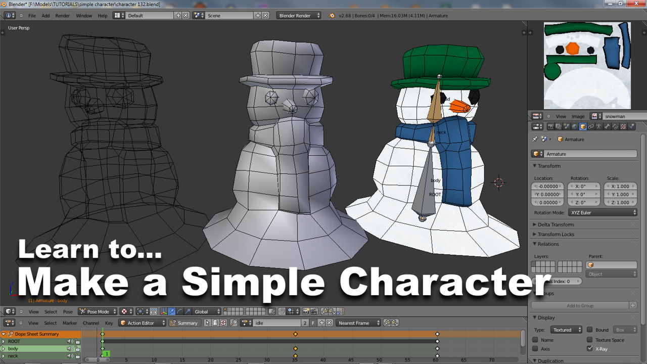
Fully rigged and ready for animation with the Armature set to “X-Ray” via the “Display” sub-section of “Object Data” properties so it can be seen in full relative to the textured mesh (it helps to see the mesh being deformed in textured mode to ensure it always articulate properly when animated [blend116]
[1: concept | 2: model | 3: material | 4: UV maps | 5: bake | 6: rig | 7: animate]

