Make A Simple Medieval High-Back Chair In 7 Steps
Learn how to make a simple Medieval style high-back chair in Blender. Breaking the process down into seven core steps, the default Scene cube object is shown edited and modified using a number common tools and techniques that will help the Reader understand the basics of making custom content for games. Familiarity with Blender is not absolutely necessary to make the most from the following but may help. Tutorial is suitable for beginners.
Download: Chair Source (c. 700 KB | *.blend, *.tga).
Design note: The below tutorial is not meant to be an exhaustive explanation of Blenders features and functions (of which there are many), it’s purpose is to guide new users on the basics of using the application by making a simple project.
Step one: basic tools
With Blender open and the default Scene available (which contains a Lamp, Camera and Cube objects), first right-click (RMB) select the Cube – it will outline orange and a ‘widget’ will appear indicating selection – and then directly below the 3D View, left-click (LMB) the selector marked “Object Mode” (see [1] below). A list will appear. Left-click “Edit Mode“. The Scene will update and the objects appearance will change slightly. This operation is one of the primary mode changes that can be done using the “Interactive Mode” selector, or more simply by pressing the “Tab” key, once to toggle in to “Edit Mode“, then again to toggle out and back into the default “Object Mode“.
Legend
– RMB = Right-Mouse
– LMB = Left-Mouse
– MMB = Middle-Mouse
– Shift + MMB = Strafe
– Ctrl + MMB = Zoom
– MMB = Rotate (Scene)
Design Note: before doing anything else take a look at the buttons and options to the right of the selector once “Edit Mode” is active. These are the most common tools and options used during the editing process to move, manipulate and change the appearance of objects and selections in the Scene;
- [1] “Interactive Mode” toggles the Scene, or selected item, between different ‘modes’ types that allows for distinct styles of editing and/or manipulation.
- [2] “Display Mode” toggles Object appearance, displaying them as colours (“Solid“), using textures (“Texture“), complex materials (“Rendered“) etc.
- [3] “Transformation Manipulators” changes and/or modifies selections (from left to right) “Transform“, “Rotate“, “Scale“. Represented in the 3D View by the “Manipulator Widget“, an ‘axis marker’ indicating the “X” (Red: left {-} / right {+}), “Y” (Green: front {-} / back {+}) and “Z” (Blue: up {+} / down {-}) axes.
- [4] “Mesh Select” used to change which element ‘type’ can be selected and manipulated, either (from left to right) “Vertex“, “Edge“, “Face“.
Zoom closer to the object (MMB scroll up or Ctrl+MMB) and readjust the Scene (Shift+MMB and MMB) where necessary so the Cube is roughly centred in the 3D View – this can be done quickly pressing “NumPad .” (period) when an object or an element is selected.
Design note: to zoom the 3D View press “Ctrl” and hold down the middle-mouse button whilst moving the mouse itself forward (zooms in, moved back zooms out), and press “Shift” while moving the mouse side-to-side and holding down the middle-mouse button at the same time (“Shift+MMB” drag). For more on navigation and Scene manipulation click here.

Most projects start from the default Scene Cube, which also has a generic Material pre-assigned that’s assigned a number of basic properties (a colour and other ‘surface’ affecting properties)

With a mesh selected and “Interactive Mode” set to “Edit Mode“, common context-sensitive functions are highlighted: [1] ‘mode’ selector, [2] ‘display’ selector, [3] manipulation modes selector and [4] element selection type selection buttons
Step 2: loop cuts
With “Edit Mode” active (“Tab“) the first thing to do is create a set of centre-lines front-to-back and side-to-side, these ensure any subsequent modifications to each half, or quarter, are uniformly distributed (as will be seen in later steps). To do this a tool called “Loop Cut” is used which places a ‘loop’ around an Object, the direction of which is determined by an initial edge selection.
Design note: the ‘loop’ aspect of a “Loop Cut” is an ‘edge’ and ‘vertex’ based element; when placed all that appears is a line that will attempt to wrap itself around the objects structure (this is not always possible, which often then results in an incomplete or ‘open’ loop). Normally when placing loop cuts, once an orientation has been selected (by mousing over a leading edge and left-clicking to select), the mouse can be further moved to select the actually location of the cut, after which left-click is used again to set the loop in place, i.e. 1st left-click selects loops orientation, 2nd left-click confirms position and sets the cut in place.
From the Tool Shelf to the right click the button marked “Loop Cut & Slide” then move the mouse back over the mesh. As the pointer passes over different edges a pink guideline appears indicating the direction a cut can be made. Hold the mouse cursor over the upper front edge of the cube and left-click. The pink guideline will change colour to orange indicating a selection has been made. It also moves with the mouse. As the loop needs to be centred rather than just placed, right-click, this forces Blender to automatically position the loop in the middle of the selected element around the entire object. Repeat the process to place a loop around the object side-to-side; click the “Loop Cut & Slide” button, hover the mouse cursor over an edge on the right side of the cube (the pink guideline will wrap around the object), left-click to set the orientation and then right-click to force Blender to auto-centre the cut (cf. first image below).
Design note: in addition to using the “Loop Cut & Slide” button, “Loop Cut” itself can be activated using the “Ctrl+R” shortcut. When initiated be aware that loop cut automatically switches selection mode to “Edge” if “Face” is active (“Vertex” in unaffected by the tool).
With the two centre-lines placed make another cut to divide the back half of the mesh, again side-to-side; left-click the “Loop Cut & Slide” button (or press “Ctrl+R“), mouse over the back half of the mesh and the edge on the right, left-click to select, right-click to set in place centred (cf. second image below). These are the initial cuts needed to then allow extrusion.

The first step is to add two centred loop-cuts front-to-back, and left-to-right to establish centre-lines – whilst not absolutely necessary using them does help ensure that ‘left/right’, ‘front/back’ modification of the mesh are equal

Add another loop-cut to divide the back half of the mesh, this creates a set of faces that can then be used to extrude the back section of the chair (the back and rear foot/leg)
Step 3: extrude
With all the initial loop cuts made the next step is to make the back and legs of the chair. This is done using “Extrude“, a generative process that creates new structure by pulling it from a selection. Before doing this the cube needs to be adjusted to form a shape that approximates a ‘seat’. Move the mouse upwards whilst holding down the Middle-Mouse button to rotate the Scene so the underside on the cube is visible (release to confirm).
Design note: depending upon how far the 3D View was rotated to expose the underside of the cube, the view may need to be rotated again for better access to, and manipulation of, the Widget tool; much of the 3D process comprises these types of manoeuvres where the Scene has to be constantly adjusted so selections can be made and tools accessed and/or used more effectively.
Then from the 3D View Header left-click the “Face” element selector button (see [4] above). The objects appearance will change to display a series of faces centred with black spots. Pressing “Shift“, right-click all the underside faces (six in total) to multi-select, then left-click-hold and drag the blue handle of the ‘transform’ widget to move the group selection upwards, decreasing the original height of the cube. Release the left-mouse button to confirm.
Design note: simple manipulations can also be done using short-cut keys instead of the ‘widgets’; pressing “G” will activate ‘free transform’ where the widget can be moved in any direction; or in combination with “X“, “Y” or “Z” to lock movement to a specific axis or orientation, i.e. pressing “G” then “Z” will only allow a selection to be moved up or down (+Z or -Z). For more on shortcut keys click here.
With that done press “A” to deselect everything, rotate the Scene back around to the top and multi-select the two back-most faces on the top side before then left-clicking the button in the Tool Shelf to the right titled “Extrude Region“. A new structure appears perpendicular to the mesh and moving with the mouse. Move the mouse upwards a short distance so the back is approximately at least twice as high as the seat area is deep, then left-click to confirm. Rotate the Scene to expose the underside of the mesh, press “A” to deselect everything, then multi-select (“Shift+RMB“) the two back most faces. Once more left-click the “Extrude Region” button in the Tool Shelf and move the mouse down so this new structure is approximately half the size of the seats depth. Left-click to confirm (the result should be similar to the first image below).
Design note: selections can be cleared pressing the “A” key (or from the “Select” menu left-click “(De)select All” as needed), which is also used to make global selections, or to ‘select all’. Using “A” to clear selections may not always be needed because the act of making a new selection automatically clears any previous – only so long as the act is not part, or continuation of a previous selection (made when the “Shift” key is pressed).
For the front legs, rather than extruding the fore-most faces as is, first select each left and right face in turn and click the “Inset Faces” button in the Tool Shelf – an inset frame will appear associated with the selection changing as the mouse moves, for precision, and to ensure both faces are equal, type “0.25” using the Numpad or standard numerical keys, then press “Enter” to confirm.
Design note: typing numerical values rather than eye-balling distances ensures any change made are uniform relative to each selection – where available it’s often easier to type a distance or size adjustment to ensure uniform accuracy.
Once both faces are inset, select each in turn once more and click the “Extrude Region” button again, or press “E” to “Extrude Selection“, move the mouse down so the front legs are approximately the same length as the rear leg section. Left-click to confirm. Once done the chair is then ready for shaping.
Design note: rotate the Scene so it’s easier to check the size of the front legs against the back. This can be done after-the-fact then pressing “G” whilst the selections are still active, or left-click dragging the blue widget handle, to make any adjustments as needed – if the legs are at different depths select one or the other and adjust as needed so they are both the same length.

Select the rear faces of the seat and left-click “Extrude” to pull the ‘back’ from the upper side, and ‘rear leg’ from the underside, of the mesh

Use “Inset Faces” to create an indented face from which the front legs are extruded – to ensure both left and right side are the same type a value, i.e. “0.25” in this instance
Step 4: Mesh Editing
Before shaping the structure, add two more loop cuts front to back – they should each pass through the front legs and wrap around to the back of the chair; left-click the “Loop Cut & Slide” button, or use “Ctrl+R“, and mouse over a front edge so the pink guideline passes through the correct orientation. Left-click to set then right-click to allow Blender to auto-centre again. Repeat so both side are the same. With the loops in place rotate the Scene so the back-underside of the chair is visible. From the 3D View Header click the “Edge” button to switch “Mesh Select” from “Face” (see [4] above). Right-click the centre edge and left-click drag the blue handle of the widget upwards a short distance, creating a triangular space in the process.
Design note: it most circumstances it’s usually quicker to change selection mode using “Ctrl+Tab” which opens the same options at the mouse cursor location via the “Mesh Select Mode” pop-up menu – edge select mode may already be active as a result of using loop cut.
Next multi-select (“Shift+RMB“) the pair of edges, front and back, to the immediate left and right of the centre (see below highlighted orange) and from the Tool Shelf left-click “Subdivide“, two additional edges will appear that, in combination with the others, can be positioned to form an arch (highlighted green below). To do this edges on either side of the centre-line are best manipulated in pairs using the “Transform” and “Scale” widget handles, for example, increase the distance between the ‘feet’ by multi-selecting (“Shift+RMB“) each inner edge (highlighted yellow below) and with “Scale” active (left-click the third widget type button with the arrows [3]), left-click and drag the Red handle of the widget. Both edges will scale away from each other increasing the gap. Press “A” to deselect and then repeat the process for the edge-pair just created (green) so their position results in an arch (multi-select, then left-click drag the widgets Red handle, release to confirm).
Design note: the rear leg is a block four faces wide by a single face in depth; a chain of four edges run parallel left-to-right and four individual edges across the depth front-to-back; the edges being selected and subdivided run side-to-side, with the new edges orientated front-to-back.
Similarly adjust the front feet so faces in contact with the ground are larger and slightly splayed apart. For this switch from “Edge” to “Face” select mode (“Ctrl+Tab“), multi-select (“Shift+RMB“) the bottom faces and then left-click drag the widgets Red handle (“X” axis) to the side slightly to increase the distance between the two selections. Release to confirm. Repeat but left-click drag the Green handle scaling the faces along the front/back axis (“Y“). Release again to confirm. Processing both groups at the same time in combination makes the feet approximately the same size and distance apart.
Design note: to access “Scale” without constantly changing the widget type via interface buttons press “S“, this activates ‘free scale’ – pressing “X“, “Y” or “Z” will lock subsequent manipulations to a given axis.
Finally rotate the chair around so the top is visible. Switch the widget to “Transform” (cf. [3] above), select the centre edge and then left-click drag the Blue handle upwards to create a peak, completing the build process.

Shape the mesh by selecting different element types (vertices, edges or faces), and using the different manipulation widgets, scale and reposition the edges created by “Subdivide” to form an arch of the rear foot, and splay (spread) the front legs slightly

The end result of manipulating the structure of the mesh is a simple high-back medieval style chair with splayed front legs and an arched rear foot with a peaked back (top)
Step 5: UV Unwrapping
With the chair shaped it next needs to be UV Unwrapped so an image can be applied. To aid in this task specific edges around the mesh can be assigned or marked with a property that causes a split in the UV Map, to which the aforementioned image is associated, with the aim of ‘flattening’ the 3D shape into a 2D layout, or ‘map’ to give it its proper name, akin to cutting a box down the sides to lay it flat.
Design note: for more on UV Unwrapping and Editing click here.
To do this first switch ‘select mode’ to “Edge” (“Ctrl+Tab » Edge“) and then multi-select (“Shift+RMB“) the following edges or groups in turn and click the “Mark Seam” button in the Tool Shelf; first mark the edges where the seat and back join, then around the top of the front legs as they connect to the underside of the seam – this will create four distinct blocks, seat, back (including rear foot), front-left and front-right legs. Next mark each section as follows; back: 1) edges running up the left-side and along the top, 2) outer left and right edges, 3) edges on the inside of the back foot and 4) outer edge of the back foot left and right side; front legs: 1) inside vertical edges of the front legs and 2) edges around the bottom of the front legs except front face; and finally seat: 1) two vertical front-corner edges and 2) bottom-side edges of the seat (see images below).
Design note: the “Mark Seam” property can be accessed using a short cut “Ctrl+E” which opens an iteration of the “Edges” menu at the cursors location. From the list of options left-click “Mark Seam“, i.e. “Ctrl+E » Mark Seam“.
Once all the appropriate edges have been marked with the Seam property the mesh can be unwrapped. For this press “A” to select everything (UV unwrapping is selection based) then from the “Shading/UV” panel of the Tool Shelf left-click “Unwrap” and select “Unwrap” from the list of options shown. This generates the necessary UV Map (not shown at this point in the 3D View). With the UV’s unwrapped and image can next be assigned to the map.
Design note: as the mesh has been edited “A” may need to be pressed twice in this instance, once to clear current or active selections (“Deselect All”), then again to reselect everything (“Select All”). This is typical of the editing process and selections in general because they remain active until deselected/cleared.

From the “Shading/UVs” Tool tab, click the “Mark Seam” button to ‘tag’ selected edges with the ‘seam’ property (which causes a split in the UV map)

For complex objects Seam placement helps unwrap the map as a flat map – it may help to first break the UV into sections and then mark each section so it flattens suitably
Step 6: textures (+UV’s)
As the original Cube had a pre-assigned Material, all that’s needed in this instance is an image, once created its then assigned to both the material and now available UV map. Much of the texture creation process can be done using a dedicated editor, the “UV/Image Editor“, which can be accessed independently, or alongside the 3D View through a change in application layout. To do this, from the main Header running along the top of Blender (often referred to as the “Info” Header) left-click the “Choose Screen Layout” selector to access the available options, clicking “UV Editing” from the list. The entire interface of Blender will change, the left side being the UV/Image Editor, the right being the 3D View.
Design note: ‘layouts’ are a convenient way to set Blenders interface to correspond to certain activities without constantly readjusting windows and views. Having said that, although each ‘layout’ is a pre-set, they are not fixed so their respective appearances can be modified whilst keeping the general ‘theme’ intact.
At the bottom of the UV/Image Editor left-click the button marked “+ New” in the Header. The “New Image” properties popup will appear. Left-click each input field and change as appropriate; type different “Name“, set a “Width” and “Height” for the image (e.g. “512” – should be a ‘power-of-two’ size), and from “Generated Type” select “UV Grid” before then finally left-clicking “OK” to generate. A grey-scale checker image will appear in the main workspace of the Image editor, but not yet assigned to the UV map or the mesh.
Design note: basically the image has to be generated before it can be assigned to the UV’s, which cannot be done unless the objects UV’s are selected, via selecting the entire mesh (the default behaviour for editing and manipulating UV’s)..
If the mesh is not selected mouse over the right side (3D View) and press “A” to select everything (assuming the mesh is still in Edit Mode, else press “Tab”), the associated UV’s will appear on the left over the UV grid, temporarily displacing the image. To assign to the UV map left-click the now visible “Browse Image to be linked” menu in the UV/Image Editor Header and select the entry corresponding to the image previously created, this superimposes the UV map over the image in the UV/Image Editor, and causes the image to appear on the model in the 3D View (press “Alt+Z” if not visible).
Design note: if the image is not visible in the 3D View change “Display Mode” to “Texture” (see [2] above), which can also be done quickly using “Alt+Z” (or “Shift+Z” for “Render” mode, “Z” to toggle “Solid” and “Wireframe“). When switching to one of the more sophisticated modes the default Lamp object will affect the contents of the Scene, shading the object – the light can either be removed (right-click, press “Delete“), or moved to a different position to illuminate new areas of the chair (right-click to select, left-click drag any one of the widget handles to move, release to confirm). For more information on creating and using Textures click here.

As the original mesh has a Material pre-assigned only an ‘Image’ is needed. In the UV/Image Editor (shown in “UV Editing” layout mode) click the “+ New” button to create a new ‘generated’ texture

Once the mesh has been UV Unwrapped the image can then be assigned – select the entire mesh in the 3D View then click “Browse Image to be linked” selector in the UV/Image Editor, selecting the previously generated image (this superimposes the UV’s over the top of the image)
Step 7: Materials (+UV’s)
Once the image is assigned to the UV map it can also then be associated with the objects pre-assigned Material. For this “Texture” Properties need to be accessed. Switch the screen layout back to “Default” selecting that option from the “Choose Screen Layout” selector in the main Header, then to the right-side of Blender left-click the button displaying a small ‘checker‘ icon, “Texture“.
Design note: it’s likely the necessary properties button is hidden from view due to Blenders default layout, so mouse over the border between the 3D View and the Properties panel, the area down the right-hand side of Blender. When the small double-headed black arrow appears left-click drag the border to the left, expanding the Properties section and exposing the previously hidden buttons. Release the mouse button to confirm. All views can be resized in this way.
Here confirm the aperture lists “Tex” then below, left-click the “Type” selector (currently displaying “None“) and left-click “Image or Movie“. The panel will update slightly with some additional properties and options. Further down in the “Image” subsection left-click the “Browse Image to be linked” button (displaying a ‘picture’ icon) and left-click the previously created image from the list. The panel will update again to display the image in the “Preview” aperture, confirming the association.
Design note: “Tex” is the name attributed to the default slot active within “Texture” properties and can be changed as needed by typing in the ‘datablock’ input field to the right of the “Browse Image to be linked” button.
With the image/material association made a final pass at the objects UV’s can be made to better position each sub-element, commonly referred to as “UV Islands“. In the Header of the UV/Image Editor switch “Selection Mode” by left-clicking the “Island” button (illustrated by an icon that looks like a ‘window frame’, cf. second image “[1]” below, the right hand button of the set of four) and then right-click the largest section of the map (corresponds to the back of the chair). Press “R” to activate “Rotate” and move the mouse to change the angle so the section is better aligned to the grid present in the image. Left-click to confirm. Optionally re-organise some of the smaller sections (front legs) so they too are better aligned or organised relative to the texture – right-click to select then press “G” to reposition elements. Left-click to confirm.
Design note: UV’s can be manipulated using the same ‘transformation’ tools as are available for the manipulation of objects and elements in the 3D View; “R” to “Rotate“, “S” to “Scale” and “G” to “Translate” ( when using shortcut keys the widgets appearance does not change to reflect the function being used). For more information on Materials click here.
Once everything is reorganised switch the Blenders layout back to the default by selecting that option (“Default“) from the “Choose Screen Layout” selector in the main Header.

Once the Image is associated with the UV map it should be linked [2 & 3] to the Material pre-assigned to the mesh through “Texture” properties [1]

With the image properly associated with the Material, the UV map can be further adjusted to align or reposition the different sections, “Islands“, using the different “Selection Mode” tools [1]
Conclusion
At this point the basic chair is done, however, using the techniques shown above it can be modified and changed in many ways, for example a simple modification might add an extra loop cut to the back so the top can be made wider (using “Scale”) without affecting the entire section (deforms from the mid-point loop cut). It’s important to remember that whatever changes are made to the mesh, the UV map is checked and adjusted to correct discrepancies introduced by editing after the fact. To optionally see what the completed seat looks like as a rendered image press “F12” (“Esc” to return to previous screen).
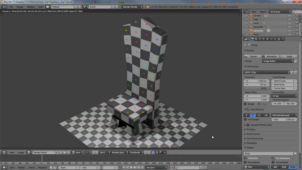
Design note: as there is only a single light source in the Scene the render will likely be too dark. To correct or adjust this right-click the available Lamp object (zoom out and adjust the Scene to view it) and duplicate (“Shift+D“) it twice so there are three Lamps (the original plus two additions). Place one front-left, another right-side, and finally one behind the object and change their height slightly in relation to the object – front at original height, side at half height, and behind at two-thirds (or three-quarters) height. Left-click the “Object Data” Properties buttons whilst a Lamp is selected and increase the “Energy:” (e.g. “1.500” how ‘bright’ the light source is) and “Distance:” (e.g. “20.000” how much the source affects) settings relative to how bright the Scene is to be rendered. Press “F12” to render and view (rendered to the UV/Image Editor), “Esc” to return and adjust values as needed. The resulting render can be saved clicking “Image » Save as Image” in the UV/Image Editors Header.

Modify the chair to make the back slightly wider by adding a new loop-cut around the extruded back (remember to re-adjust the UV map to make sure the image sits properly over the mesh without significant distortion – some may always be present due to the complex shape of the chair)
")
Final chair rendered (“F12“) using a simple three-point lighting system (flat plain added to the Scene as a floor – “Shift+A » Mesh » Plain“). Shown in the UV/Image Editor

Full render saved externally as an image
Video
Video in real-time showing the process explained above from start to finish (minus rendering).
Walk-through showing the process of making the simple medieval style high-back chair from start to finish

