Game Assets & Collision Meshes
One of the most challenging aspects modelling content for games is their optimisation, making detailed objects for the player to enjoy whilst keeping the overheads associated with rendering such items to a minimum. In this regard “Collision Models” are a useful tool, simplified structures that encase more complex objects, handling collision and other real-time physics based interactions. Although relatively straightforward to use there are a number of important consideration to keep in mind when doing so.
The following discusses Collision Models relative to using Blender to make content for games although the general principle apply to other 3D modelling applications. Familiarity with Blender is useful but not specifically required.
Download: Collision *.obj Example (c.250 KB | *.blend, *.tga).
What is a collision mesh for
Generally speaking “Collision Models” are used to reduce the amount of effort a game engine expends rendering a scene whilst the player moves around and interacts with it; the more complex the world, the higher the resource demands, to the extent that some form of collision reduction is an eventuality. In other words collision models are essentially a resource optimisation, they allow for basic collision and player interaction whilst keeping processing overheads to a minimum. A pillar comprising 500 triangles without collision for example, would mean each individual face being used to calculate player interaction when, given the objects basic shape, a fancy cylinder, an even simpler structure might suffice. This would then reduce the general overheads associated with the game-model (what the player sees in-game), freeing up inefficiently used resources for other processes. Across and entire level, such savings can be significant.
Design note: although generally referred to as “Collision Models“, “Collision Meshes” and/or “Collision Hulls” can also be used interchangeably to mean the same thing – the difference is ostensibly one of context; in Edit mode the structure will often be called a ‘collision MESH‘, in Object mode a ‘collision MODEL‘ simply due to the nature of each mode. Discussed relative to an individual model however, ‘collision MESH‘ or ‘collision MODEL‘ might be appropriate, whereas for larger objects, or even entire levels, ‘collision HULL‘ may be preferable. In all instances ‘MODEL’. ‘MESH’ and ‘HULL’ mean the same thing in terms of the object being referred to and its general purpose.

Collision models are essentially low-resolution versions of a paired ‘parent’ object which allow the latter to be more detailed than the former without the overheads associated with calculating physics and other interactions for complex items and densely populated scenes
How are Collision meshes used
As discussed briefly above, collision models are a form of resource optimisation. To this end they are primarily simple structures made from basic ‘convex‘ shapes, often subject to a triangle limit, and are usually exported as part of a model, or occasionally as independent objects.
Design note: ‘concave’ collision hulls may be possible if collision is a ‘skin‘, else they tend to made from a collection of ‘convex‘ shapes. This means clipping organic objects typically necessitates collision hulls be broken down into a collection of other objects grouped together (shown below).

Collision meshes are typically ‘convex’ shapes[1] although ‘concave'[2] is possible depending in engine requirements, else they need to be broken down into ‘convex’ blocks and grouped together[3] to get the desired result
How this is done largely depends upon the mechanism of identification utilised by game engines and development environments to determine ‘collision’ and ‘non-collision’ elements of a model or models which, in Blender, might comprise multiple meshes with multiple materials prior to export. Commonly this sort of delineation is defined by Material, Mesh or by Object.

A collision model generally encompass another model of similar shape or structure and is usually formed by ‘primitives’ – basic shapes. Depending on the level of interaction needed, they’re typically conform to the underlying model loosely so overlap and under-lap is typical

Shown in Blender prior to export, a rock tunnel prefab is split into its constituent parts – a series of meshes representing different aspects of the overall model, each of which is UV mapped and has a unique Material and Texture assigned (one per mesh)
Collision as sub-Mesh
When collision needs to be included as a component of a model, output needs to be formatted so the resulting file contains a series of “Sub-Meshes“. The way this is done generally requires individual meshes to be collated and exported, at which time they are merged together to form a single game-model whilst keeping the respective material and geometric data for each element separate. In other words, from Blender this would mean structuring the model similar to the following for a single object that has clearly defined collision sub-mesh;
- Corridor object
- Corridor (merged floor, walls and hull meshes [*])
- Collision
Or where multiple objects are to be exported with collision, all as sub-meshes, like so;
- Corridor object
- Floor
- Walls
- Hull
- Collision
This subsequently means the collision element can be independently marked and identified, usually through the application of a special ‘tag’, for example exporting models for Unreal would mean tagging collision element in Blender (or after manually editing the file where possible) with the special “UXC_” prefix, i.e. “UXC_corridor“. Or alternatively through assignment of a ‘collision’ material that similarly identifies the appropriate surfaces. Either way the end result should be a clearly marked sub-mesh within the final file.
Design note: to ‘name’ or ‘tag’ an object in Blender; for 2.49 or below select the object and check the “OB:” input box in “Links and Materials” (“F9“). Change the entry to “UXC_[meshname]”. For Blender 2.50 and above (up to and including the latest version), select the object and then click the “Object” Properties button. Enter a name in the input field at the very top of the panel. Check case sensitivity when naming items, some game engines don’t care about upper/lower casing, others do, i.e. “UXC_” might not be the same as “uxc_“.


Where collision needs to be a separate sub-mesh this likely means other meshes will need to be joined together to form a single ‘subject’ mesh (what the object is, a ‘corridor’ or ‘pillar’ for example), or be left as distinct units within the overall file. Both approaches produce delineated files where each item is clearly defined in the files data structure
Collision as Material
The alternative to sub-meshes is to merged everything together. This differs in that, whilst there is similarly a single game-object, the geometric and material data associated with what were individual meshes in Blender, is collated at export and merged into a single ‘MESH’ instance in the file rather than being separated elements, i.e.;
- Corridor object
- Corridor (merged floor, walls, hull and collision meshes [*])
The natural consequence of this is such that collision can’t be tagged directly so it has to be done indirectly through the use of a collision Material, an identifier applied to specific surfaces though Material assignment and/or UV mapping.
Design note: in Blender the application of a collision material to surfaces in this context would simply be for identification purposes. In other words, unless specifically required (and/or available for export), there is no need to associate any additional Properties or parameters to the Material.

 When collision and game-mesh are merged into a single object, the former is identified through the application of a ‘collision’ Material – correct assignment of materials is important in this regard
Collision as Separate Object
Alternatively collision can be exported as an object independent of the game-model it clips, both then being paired up in an editor. Notwithstanding ‘sub-mesh‘ or ‘material‘ definitions as discussed above, in this context collision would then be structured similar to the following if sub-meshes are to be merged together;
- Corridor collision
- Collision
- Corridor object
- Corridor (merged floor, walls and hull meshes)
Or when the game-model contains sub-meshes;
- Corridor collision
- Collision
- Corridor object
- Floor
- Walls
- Hull
In either instance the separate collision object will still need to be identified as such, typically through the application of an ‘collision’ material, per merged meshes, or by tagging the mesh appropriately (not necessarily the ‘object’), per sub-meshes.
Design note: with collision being a completely separate object this also means exporting a ‘sub-mesh‘ or ‘merged‘ game-model without collision is valid so either/or will need to be verified against the games requirements. In addition, even though the collision object contains a single mesh instance, it may still need to be ‘named‘ as if it were part of a collection so the ‘tag’ is present. Collision models should also not typically contain extraneous Material references, textures or sub-meshes and will be subject to aforementioned limitations on physical complexity per requirements.

 section and collsion objects for separate export")
When collision needs to be a completely independent object its typically exported separately from the main game-model resulting in a ‘pair’ or ‘set’ of assets that are teamed up in the game development suit or editor – the collision model should contain no other elements; materials, textures or sub-meshes
Multi-Materials or multiple materials
Aside from the way meshes are collated together, the format they are subsequently exported to also plays a role because it may be subject to some inherent limitations, or those superficially imposed by the engine within which files are to be used. In practice this means that whilst a game-model might be exported with sub-meshes and multiple materials, the format used might actually limit this to a merged mesh with a multi-material. In other words a merged game-model referencing a ‘multi‘ material is typically structured as follows;
- Corridor object (multi-material)
- corridor.mesh (merged floor, walls, hull and collision [*])
- floor.material
- wall.material
- hull.material
- collision.material
- corridor.mesh (merged floor, walls, hull and collision [*])
Whereas an object with sub-meshes and ‘multiple‘ materials might be structured like so;
- Corridor object (multiple materials) [*]
- floor.mesh
- floor.material
- wall.mesh
- wall.material
- hull.mesh
- hull.material
- collision.mesh
- collision.material
- floor.mesh
To confuse the matter further, where collision is to be an independent object, and the game-model is to make use of sub-meshes, the two items separately might be structured as follows;
- Collision object
- collision.mesh
- collision.material
- collision.mesh
- Corridor object
- floor.mesh
- floor.material
- wall.mesh
- wall.material
- hull.mesh
- hull.material
- floor.mesh
Which is not functionally the same as collision with a game-model made from merged meshes and a multi-material like so;
- Collision object
- collision.mesh
- collision.material
- collision.mesh
- Corridor object
- corridor.mesh (merged floor, walls and hull)
- floor.material
- wall.material
- hull.material
- corridor.mesh (merged floor, walls and hull)
If the engine or development environment requires separate objects for both game model and collision but cannot read multi-materials, then some way of merging both meshes and materials into a single instance will need to be found.
Design note: when merging materials and meshes to create unique assets, texture density can be an issue, especially where such assets are to match other components in the environment; a corner section with unique texture assignment having to match a corridor using tiled textures for example, the disparity between the two might be noticeable in-game.
In other words should a model need to comprise a single mesh and single material that would otherwise contain multiples instance of either, the creation of a ‘unique’ asset is likely, i.e. a model with a material and texture assignment unique to that object like so;
- Collision object
- collision.mesh
- collision.material
- collision.mesh
- Corridor object
- corridor.mesh (merged floor, walls and hull meshes)
- corridor.material (merged floor, walls and hull materials)
- corridor.mesh (merged floor, walls and hull meshes)
Design note: essentially no matter the internal structure of the resulting model, there must always be a way for collision to be identified. Where the export format has a direct bearing on this some testing will likely be necessary, *.ase (ASE) models are a case in point as whilst the format itself is quite comfortable natively supporting sub-meshes or multi-materials, different game engines are not; ASE used for Unreal for example prefers merged meshes and multi-materials like so (note that *.ase files are obsolete for Unreal editing post-UE3, which now has preference for *.fbx);
- Corridor object
- collision.mesh
- collision.material
- corridor.mesh
- floor.material
- walls.material
- hull.material
Whereas ASE for idTech is looking for sub-meshes and multiple-materials like so;
- Corridor object
- floor.mesh
- floor.material
- wall.mesh
- wall.material
- hull.mesh
- hull.material
- collision.mesh
- collision.material
(with idTech in particular, there’s a sub-mesh and material limit so game models cannot contain an unlimited number of either. This may also hold true for other engines, development environments irrespective of the models format, i.e. *.obj, *.fbx, *.3ds etc., so care should be taken to make allowance for this). The net result of this difference is that if an Unreal *.ase is opened into an idTech game the first material referenced will be applied to the entire model rather than to specific areas. Whereas if an idTech *.ase is opened into an Unreal game, the sub-meshes and materials may be merged (which can break Smoothing).
Collision mesh structure
As briefly discussed above the shape and complexity of a collision mesh is usually subject to significant limitation, primarily to reduce the amount of resources used calculating real-time collision and player interaction physics. For most types of regularly shaped object, conforming to these requirements is relatively straightforward because simple primitive shapes, cubes, cylinders etc., are able to encase models without breaking player immersion. Organic or irregularly shaped structures on the other hand often can’t be clipped quite so easily using primitives so inevitably a compromise has to be reached whereby collision surfaces approximate the basic structure without the player being kept too far away from the game model, or conversely finds themselves able to clip through into the void.
Design note: the player has to be able to get close enough to a surface so they ‘feel’ like it can be touched, if not and they are held too far away, the detachment that imbues breaks immersion. Similarly their clipping through the world and seeing ‘the void’ (not withstanding this potentially revealing areas of a level they might not otherwise have known about).


Regularly shaped objects (upper image) are relatively easy to clip with collision because they can be encased inside a ‘primitive’ without breaking immersion (preventing the player getting too close). Organic or irregularly shaped objects require a compromise that depends on the level of interaction expected of the player, which can mean the collision mesh being of varying complexity (lower image) – note also the difference between collision as a ‘skin’ (bottom image) versus collision as a ‘volume’ (upper image)
Collision as Open or closed mesh
Collision meshes by nature are relatively simple shapes and once an object or element has been identified for use as collision, how this manifests in game differs based upon whether the property is attributed to a ‘surface‘ or ‘volume‘, which then determines the kinds of structures that can be used, and whether they can be ‘open’ or ‘closed’. What this means in essence is that open meshes tend to be ‘surfaces‘, ‘skins‘ or ‘layers‘ that are not always intact or complete relative to the model being clipped. Whereas closed meshes are more often ‘containers‘, ‘volumes‘ or ‘blocks‘, sealed units that typically encase objects.
Design note: an ‘open’ mesh is one considered to have gaps or open faces – if liquid were poured into such a mesh it might flow through or out an ‘open’ face or area. A ‘closed’ mesh on the other hand is completely sealed – liquid inside would not spill out because its trapped within the structure.
What this difference means in practice is that ‘closed’ meshes are often easier and cheaper to use but less versatile, they work well for formal structures but not for irregular or especially organic shapes, which might better suited to being clipped by ‘open’ meshes. And this presents a particular problem; because clipping tends to reduce the amount of room available for the player to move around, a passage once clipped might become too narrower to the point of making the item unusable. Compensating for this loss then needs to be thought out prior to construction to avoid having to remake what might be some very complex models.
Design note: the difference between the two in practice is such that open meshes tend to consider surfaces (triangles) as being meaningful with respect to collision, whereas for closed meshes a ‘volume’ or ‘area’ predominates (‘surfaces’ define the boundary of a volume). This distinction can also have an affect on material assignments because although highly dependant on the structure of the game-model, materials might then act as surface properties indicators, visual identifiers, or some combination of both. Collision in idTech for example is volume based, material assignments simply identify collision ‘types’ – player, weapon, bot etc. – and display such surfaces as invisible to the player. In doing so they have no affect on the fundamental structure of the brush itself; without materials brush volumes are simply ‘blank’ grid coordinates that define an area without a function, the volume is effectively ‘null’. Collision in Unreal on the other hand is often determined by models (although Unreal Editors internal Collision editor is recommended) identified for that purpose based on the application of an object assigned tag (“UXC_[meshname]” etc.) which then registers surfaces as the actual element of collision (depending on the collision objects shape, the player actually collides with its surfaces rather than the object itself, even though the latter has the identifying tag assigned). Similarly in Unity, collision can be assigned as an ‘object’ property using surfaces as the actual element with which the player interacts.
, the other a 'skin' (right)")
In practice collision is usually either a ‘skin’ (right) or composed of a series or shaped ‘volumes’ (left). There are advantages and disadvantages to either but using block generally necessitates a greater need to make allowance for the amount of space used due to their perpendicular orientation
Collision, UV maps & textures
Collision meshes, like other types of custom content, should be UV mapped with an image assigned, often as a temporary placeholder. UV mapping is not specifically representative of anything, collision surfaces or structures are never seen in-game, consequently unwrapping need not be done to any particular degree of fidelity other than their being a UV map and image assignment for identification purposes.
Design note: collision meshes need to be UV mapped largely so the export process completes; output will generally halt or fail showing a “no UV ” error of some kind as meshes without UV’s are typically considered ‘broken’.
In UV unwrapping collision models care should be taken as to whether UV’s have to be mapped within the available “texture space“, the “0,0/0,1/1,1/1,0” texture bounds that define the default area and behaviour of the map. In other words it may be a requirement that UV maps not extend beyond the boundary of image left, right, top and bottom else they clip, invert or are subject to some other compensatory deformation.
Design note: the “0,0/0,1/1,1/1,0” coordinates correspond to the UV mapped corners of an image – “0,0” is bottom-left, “0,1” bottom-right, “1,1” top-right, “1,0” top-left – which define the default “texture space“, essentially the area within which a single instance of an image will sit. Depending on the way textures are mapped by the game engine, UV vertices outside the bounds defined by these coordinates might be treated in a way that corrupts the map, they can be flipped back in on themselves for example.

A ‘skin’ based collision object is UV unwrapped so the map extends beyond the “Texture Bounds” area in the UV/Image Editor – depending on game engine technicalities this may cause problems where the image only appears in a small area, or the map may be mashed up as UV vertices outside the defined area are wrapped back in to ‘valid’ space resulting in a distorted mess

Alternatively the collision mesh UV’s can be mapped so they fall within the “Texture Bounds” area – whilst this does mean the UV’s are ‘valid’, depending on the size of the image being mapped, may result in collapsed vertices, especially if “Pixel Snap” is active
Conclusion
For custom content, modelling collision is often the best option to get the most from collision systems because it allows for a more tailored approach to a common problem. It does have some limitations however, primarily that it can only be formed from simple shapes, and may occupy more space than the mesh being clipped describes, a point of particular note for organic structures or forms that are not expressly perpendicular to the world (overhangs, under-hangs and other odd shapes and structures). This requires consideration, often meaning narrow corridors made that way for visual effect, have to be widened to allow proper access by the player once the game-model is clipped with collision. This does of course depend on whether collision should be a skin versus blocks. Preference should be given to investigating this, and other limitation/requirements, prior to beginning any modelling to avoid having to correct issues later.
Export examples
The following are examples of the kinds of structure typically resulting from the above discussion. First a collection of separate meshes are exported and collated together to form an *.obj file containing several sub-meshes, each with an associated material reference (extensive mesh data is excluded for convenience/clarity);
(items marked "o" represent individual sub-meshes)

	o collision
		[... mesh data ...]
		usemtl collision
			s off
			f 2/1/1 4/2/1 3/3/1 1/4/1
			f 4/1/2 8/2/2 7/3/2 3/4/2
			f 8/1/3 6/2/3 5/3/3 7/4/3
			f 6/1/4 2/2/4 1/3/4 5/4/4
			f 1/1/5 3/2/5 7/3/5 5/4/5
			f 6/1/6 8/2/6 4/3/6 2/4/6

	o back
		[... mesh data ...]
		usemtl back
			s off
			f 11/5/7 9/6/7 10/7/7

	o right
		[... mesh data ...]
		usemtl right
			s off
			f 12/8/8 14/9/8 13/10/8
	o front
		[... mesh data ...]
		usemtl front
			s off
			f 15/11/9 17/12/9 16/13/9
	o left
		[... mesh data ...]
		usemtl left
			s off
			f 18/14/10 20/15/10 19/16/10
	o base
		[... mesh data ...]
		usemtl base
			s off
			f 21/17/11 22/18/11 23/19/11 24/20/11
Next meshes are merged so export produces a sub-mesh for collision and game-object;
	o collision
		[... mesh data ...]
		usemtl collision
			s off
			f 2/1/1 4/2/1 3/3/1 1/4/1
			f 4/1/2 8/2/2 7/3/2 3/4/2
			f 8/1/3 6/2/3 5/3/3 7/4/3
			f 6/1/4 2/2/4 1/3/4 5/4/4
			f 1/1/5 3/2/5 7/3/5 5/4/5
			f 6/1/6 8/2/6 4/3/6 2/4/6

	o front
		[... mesh data ...]
		usemtl right
			s off
			f 12/5/7 14/6/7 13/7/7
		usemtl front
			f 15/5/8 17/6/8 16/7/8
		usemtl left
			f 18/5/9 20/6/9 19/7/9
		usemtl base
			f 21/8/10 22/9/10 23/10/10 24/11/10
		usemtl back
			f 11/6/11 9/7/11 10/5/11
And then finally all meshes are merged into a single unit;
	o collision
		[... mesh data ...]
		usemtl collision
			s off
			f 2/1/1 4/2/1 3/3/1 1/4/1
			f 4/1/2 8/2/2 7/3/2 3/4/2
			f 8/1/3 6/2/3 5/3/3 7/4/3
			f 6/1/4 2/2/4 1/3/4 5/4/4
			f 1/1/5 3/2/5 7/3/5 5/4/5
			f 6/1/6 8/2/6 4/3/6 2/4/6
		usemtl right
			f 12/4/7 14/5/7 13/3/7
		usemtl front
			f 15/4/8 17/5/8 16/3/8
		usemtl left
			f 18/4/9 20/5/9 19/3/9
		usemtl base
			f 21/6/5 22/7/5 23/8/5 24/9/5
		usemtl back
			f 11/5/10 9/3/10 10/4/10

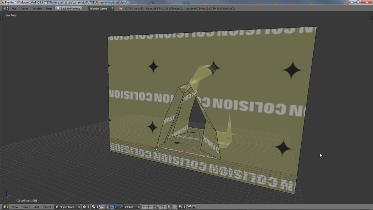
The example file shown in code above is a simple pyramid object encased in a cube primitive for collision. Each side is separated and then exported according to whether the resulting *.obj should contain sub-meshes and associated materials or single mesh with multi-material

