Texture Bake Normal Maps from High-poly meshes in Blender 2.49
Generally speaking there are two approaches to generating “Normal Maps” for games depending on their eventual ‘use’ which, to use borrowed terminology from idTech, equate to “renderbump” – the rendering of unique images for application to low poly versions of the same rendered mesh, and “renderbumpflat” – rendering Normal’s to flat surfaces for use as tile-able textures. Although the same model can be used for both, the way each needs to be set up differs respectively. Producing textures for both purposes can be done in Blender through use of its “Texture Bake” rendering sub-system.
The following is written with Blender 2.49 or below in mind. To get the most from the following materials its best a basic understanding of Blender be had beforehand; being able to move and manipulate objects, change views and select options is necessary. It is also assumed pre-made assets are available and ready for use as the information below does not discuss how to make high resolution 3D models.
Texture Bake Basics for Normal Maps?
Because of the way Normal maps are baked, explained below, for this to be performed successfully two prerequisites are needed (rendering baking cannot be done without the following);
- A low poly or ‘game ready’ mesh.
- A high poly ‘art’ mesh.
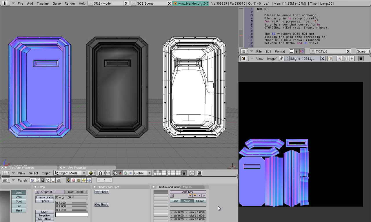
The low poly ‘game ready’ mesh is a low resolution version of the baked model solely for use in-game, in this instance a ‘tech’ door (shown on the left of the image below marked “low poly”). This object should to be optimised relative to its target use and must have; at least one Material assigned with a Texture and Image slot; be fully UVW unwrapped; mapped to the assigned Material/s image/s.
The “high poly ‘art’ mesh” is a high resolution, high density object built specifically for the purpose of texture baking; the structural and geometric detail contained forms the basis upon which normalised data is generated and baked to the image wrapped around the low-poly mesh. In the image below this is the object marked “high poly” on the right.
Design note: A third version of the model is often used, called the “control cage“, this is optional and more to do with work practices as it allows for the creation of both a high and low poly mesh from the same core data.
 doorway")
Generally speaking only two meshes are required for texture baking, a low-poly ‘game’ mesh (left) and a much higher density ‘art’ mesh (right) – the item in the middle is a “Control Mesh” from which the low and high resolution meshes can be made as simple adjusted iterations of said-same
Mesh Preparation: Materials, Textures, Images & UVW’s
Because the high resolution object is effectively baked to the low (or rather the image mapped to it), there needs to be a way for the baking process to understand what it’s supposed to be doing in relation to both objects. In other words, Blender needs to know where it’s supposed to ‘bake’ (‘write’ or ‘paint’) the coloured pixels that represent the high resolution mesh’s normal’s; which areas of a mapped image should contain baked normals and which should not. This is what the UVW map on the low-poly object is for, the unwrapped layout determines where bake data is written. For this reason its crucial the low poly mesh have a functional and properly mapped UVW.
Design note: the bake process does not work in absence of an Image to which bake data is written. Additionally, the Image to be used cannot be assigned to the UVW in isolation of a fully formed Material, one that contains a ‘Material’, ‘Texture’ and ‘Image’ slot otherwise Blender will report an error or the mesh will appear unaffected by subsequent rendering.

Make sure the low-poly mesh has a fully formed Material assigned that has a ‘Texture’ and ‘Image’ slot – the image can be a bitmap or ‘Generated’ data (usually a “UV Test Grid” created from the “UV/Image Editor“)
Shown below for example is a tech door with its UVW mapped to an assigned image; the UVW layout itself can occupy as much or as little space as is needed, especially if the same map is to be used by other objects, but must be contained within the bound of the available space to prevent issue with the resulting bake. Again note shown is the low-poly version, the high resolution mesh does not require a UVW map or Material/Texture/Image assignment.
Design note: keep in mind that depending on how many assets need to be UVW unwrapped and normal map baked, the distribution and amount of space available for use by any given individual object will need to be adjusted where appropriate.


Low poly door model showing UVW map active in both the 3D view (left)and image/UVW edit view (right) – although the overall mapping is ‘unique’ (specific to the object) the upper image shows what’s typical of a ‘shared’ map that occupies a section of a larger map (that might belong to other objects), the lower image uses the entire texture space (which generally means a better quality render)
Before UVW unwrapping the low-poly mesh then, assign at least one “Material” that similarly contains at least one “Texture” and one “Image” slot. To do this in Blender 2.45 (only) RMB select the mesh and press “F” to enter “UV Face Select” mode. Press “A” to “Select All” (this may need to be done twice, once to de-select prior selections and then again to re-select everything). Next press “U” to access the “UV Calculation” pop-up menu and select “Unwrap“. This will generate a basic UVW map for the object.
Design note: the “Texture Bake” feature used to render Normal maps as discussed in this tutorial is only available in Blender 2.45 and above – earlier versions are not supported.

In Blender 2.45 UVW mapping is done in “UV Face Select” mode. Once there press “U” to access “UV Calculation” and then select “Unwrap” from the list of options to generate an initial UV layout which can then be edited in the “UV/Image Editor”
To effect the same in Blender 2.49 (or below), with the mesh selected, RMB, press “Tab” to enter Edit Mode as would be done normally when editing the mesh. Press “A” to “Select All” (again this may need to be done twice as per above) then “U” to access “UV Calculation” options, finally clicking “Unwrap” from the list to generate the initial UVW map.

In Blender 2.49 UV unwrapping is done in Edit Mode so the dedicated mode of 2.45 and previous is no longer available. To unwrap a mesh select the entire mesh and then press “U” to access the unwrapping options; for a standard map select “Unwrap” from the list
Absent any “Seam” markings or mesh splits the initial UV layout may be a jumble of elements so some time will need to be taken to organise the map in the “UV/Image Editor” so it has as little distortion as possible and occupies the amount of space needed (depending upon it sharing the texture sheet with other assets).
Design note: to edit the UV map Blenders interface can be changed to make the process easier to do so either; divide the interface (RMB click on a window divide, select “Split“) so a separate “UVW/Image Editor” can be opened; or switch to that view (“Shift+F10“). In either instance the newly created UVW map should appear superimposed over the top of the image that’s assigned to the material (if not select it from the “Browse existing…” drop-down menu) – press “Alt+Z” to toggle the display of the texture on the model to check. In the “UV/Image edit” view, press “A” to select UV faces (may need to be done twice as mentioned above), and then “S” to initiate “Scale“, simply move the mouse to scale the selected UVW map up or down, LMB to set the move. For more information on UV unwrapping and editing UV maps click here.
Mesh preparation: Location, Origin, Scale
Texture baking is a ‘like for like’ process so it relies on objects occupying the exact same XYZ co-ordinates ‘globally’, i.e. their position relative to the Scene, and ‘locally’, i.e. the shape, size and location of the individual objects themselves. In order for texture baking to work correctly both high and low resolution meshes need to;
- Occupy the same location in the Scene.
- Be the same size.
- Both have a scale value of “1”.
- Use the same Object Origin point.

Low poly mesh shown relative to the ‘XYZ’ axis in Blender – note that the position of the Origin point is not critical in the sense that it needs to be centred on the 0,0,0 grid; what’s important is that both the high and low poly mesh use the same point co-ordinates

The high poly mesh shown placed at the same ‘XYZ’ co-ordinates on Blenders grid as the low poly version; note again the position of its Origin point – co-located with the low poly version
Before doing anything to object Origin points its best to set the “Scale” to their default value, “1.000“. This then ensures that any changes to the meshes are identical in terms of their units of measurement – if each items is scaled differently, when resized the values are relative to the objects ‘scale’ rather than it’s physical size. To correct this, select each mesh in Object mode and press “Ctrl+A” to access the “Apply Object” options selecting “Scale and Rotation” from the options available (or select “Object » Clear/Apply » Apply Scale/Rotation” from the 3D View Header). Check “Transform Properties” and make sure the “Scale” values on the “X“, “Y” and “Z” axes are set to “1.000“.
Design note: in Blender 2.45 pressing “Ctrl+A” brings up a confirmation dialogue rather than an options menu so selecting “Apply scale and rotation” confirms the operation. In Blender 2.49 the same shortcut brings up a list of options from which a selection can be made – in most instances this should be “Scale and Rotation to ObData“. In either instance this will reset the objects “Scale” values on the “X“, “Y” and “Z” to “1.000”.

Make sure that “Apply Object” data is set before using texture bake as they are affected by the respective positions, sizes and scales and Origin points of the objects being baked
Once Scale has been set on both objects then can be repositioned using standard manipulation tools so they occupy the same space and then their respective Origin point reset. It is crucial at this point for both versions of the model to occupy the same location, any discrepancies here typically result in bad normal’s being calculated and baked, so take time to ensure both are collocational.
Design note: when moving objects in either ‘Object’ or ‘Edit’ mode, holding “Ctrl” whilst doing so will snap movement/manipulation to the grid, “Ctrl+Shift” to smaller increments.
")
Both the high and low poly mesh are collocational., they occupy the same place in the Scene: this is important to ensure normal’s are properly calculated and baked, any discrepancies between the two will result in bad normal’s
Once both meshes are arranged correctly with respect to each other their Origin points should be set so they too are collocational. The more effective way to do this is to set their location using the Cursor as this allows for much greater positional control independently of the objects themselves. There are two options; 1) setting both Origins to the cursors location, or 2) using the Origin from one object as the position for the other. In either case the Cursor is the point to which the respective Origin points snap.
To do this for the first option the cursor needs to be positioned independently by setting it’s “X“, “Y” and “Z” location values in “View Properties“. In the 3D View Header click “View » View Properties…” and in the panel that opens edit the “X“, “Y” and “Z” values under “3D Cursor” to “0.00” respectively. The Cursor will move to Blenders grid centre (“0,0,0“). Once positioned select each object in turn (whilst remaining in ‘Object’ mode) and from the “Mesh” properties panel in “Editing” properties (“F9“), click the “Center Cursor” button. The selected objects Origin will reset to the cursors current location. Applied to both object this now means they use the exact same Origin coordinates.


Set the Cursor location by editing its “X”, “Y” and “Z” coordinates – this positions it in space. Then click the “Center Cursor” button to (re)set the selected objects Origin to the cursor. This needs to be done for both meshes so they use the same Origin point
For the latter option, using one objects Origin point as the position for the other, select one of the meshes and then press “Shift+S” to access the “Snap” menu options (or click “Object » Snap” from the 3D View Header). From the list select “Cursor – > Selection” (cursor to selection). The Cursor will immediately relocate to the selected objects Origin point. Finally, and as above, select the remaining object and click the “Center Cursor” button in “Mesh” properties to reset the remaining objects Origin to the cursor, matching the initial mesh whose ORigin point was used to snap the cursor.

Using one of the objects to be baked, set the Cursor’s location to the selected items Origin with “Cursor -> Selected” from “Snap” options and then reset the remaining objects Origin to this new location using “Center Cursor” in Mesh properties
Once the above has been applied to both meshes, co-location can be confirmed, somewhat ironically, by the presence of what is usually regarded as a ‘visual artefacts’ error and best avoided; “Z-Fighting” as this is called, is the result of a conflict between co-planar surfaces being drawn to screen at the same time – if they are exactly co-planar (exact same place/location), the ‘fight’ to be drawn to screen results in a visual flickering. If this occurs after making the above adjustments it tends to mean both meshes are set up correctly and ready for the Normal map/s to be baked.
Design note: do not skip the above steps – it’s important to make sure the low poly mesh has a good, clean UVW map, that both objects are in the exact same place, and are exactly the same size and dimensions; taking short cuts and ignoring the above will result in poor render results and wonky renders (for more on this see the ‘advanced’ section).

The light and dark patchwork visible in the above (mainly across the flat inner face of the door) is “Z-Fighting“, a rendering issue due to Blender not being able to determine which surface should be drawn on screen; when this happens the two surfaces ‘fight’ with each other for priority resulting in a flickering visual artefact (users with PSE should be aware the sometimes rapid flicker might trigger a reaction)
Baking & Saving Normal Maps
Once the objects have been appropriately set-up in the 3D View, baking the Normal map is relatively straightforward; both meshes need to be selected, a few basic options are set and finally a ‘render’ button clicked to start the process. Having said this, the order in which the meshes are selected is important. Because the process is baking the high resolution Normals to the low, the former much be selected first, and the latter last – RMB select the high, then “Shift+RMB“ the low – this makes the last object selected the “Active” element (highlighted with a lighter pink outline). With this done, in “Scene” properties (“F10“) click the “Normals” button to set the render type, “Selected to Active” to make sure the render ‘order’ is set and then click the “BAKE” button to start the process, which will be shown in the UV/Image Editor if visible.
Design note: the “Choose normal space for rendering” option should default select to “Tangent“, if not choose that from the list if ‘tangent’ normal maps are required, as is typical of most game related content. Other setting that can be used include “Clear“, which forces Blender to wipe render memory, and “Margin“, which creates a ‘buffer’ around each baked area to help mitigate issues relating to what would otherwise be exposed borders.

To bake the normals select the high resolution mesh first, then the low – the low-poly mesh should be the active element. Then select “Normals“, make sure “Selected to Active” is on and click “BAKE”
Make sure the low-poly mesh is UVW mapped relative to it’s eventual use and that an image has been assigned before clicking the “BAKE” button
It’s important to understand the data produced by the bake process is temporary in nature and cached in the applications memory as a dataBlock, similar in fact to other forms of generated data, it has to be saved to an appropriate format for it to be ‘made real’. This is done from the “UV/Image Editor“. If not visible switch an open window by selecting the editor from the “Display type…” drop-down list far-left of a Header (or press “Shift+F10” with the mouse cursor over a view). Shown by default will be the Normal map just rendered. From the Header click “Image*” then “Save As…“. The “File Browser” view will appear. Choose a format from the “Save Image as:” list, rename the file and change the save location and then click the “Save Image” button top-right. Blender will write the data to disk and then return to the UV/Image Editor.
Design note: the Header item, “Image“, appears with an appended “*“, “Image*“, indicating there is image data in the buffer needing to be saved. Once done it’s removed and the menu option reverts to “Image“. When saving the generated image data to an uncompressed or loss-less format such as TGA, TIF, BMP etc., rather than JPG because the latter makes use of lossy compression which introduces artefacts that tend to cause quality issues. For Normal maps especially avoid any such formats use altogether because the resulting artefacts cause rendering issues due to colour aberrations.

From the “UV/Image Editor” click “Image*” to save the baked data to file. In the “File Browser” that opens select the format, change the name and same location where needed and then click “Save Image”

The final baked Normal map shown in UV/Image Editor
Conclusion
Using Blenders own internal normal map render capabilities is a quick way to generate game ready normal maps and providing the steps above are followed there aught not be any major problems – most render related issues often need simple ‘tweaks’ to fix.
There are caveats to baking Normal Maps in Blender however, which are discussed in the advanced section.

