Bake Normal Maps from Meshes
Blenders default render engine, “Blender Render” or “Blender Internal” as it’s often called, includes a dedicated sub-system that can be used to generate various types of image map, typically of an object in of itself (direct or self-referencing), or by translating the details of one to another (indirect or inferred referencing). This latter approach is most often used to create Normal maps, a process whereby the detail of a high-resolution model is rendered down, or “Baked“, to an image UV mapped to a low resolution version of the same mesh.
The following tutorial discusses this process, of using “Blender Render” and the “Texture Bake” sub-system to generate a Normal map from a high-resolution mesh. A basic understanding of Blender is useful but not specifically necessary to get the most from the below.
Design note: the "Texture Bake” process is much the same in principle as for Blender 2.49 or using Cycles Render although it differs somewhat in process. i.e. which buttons are pressed, when and where.
Low-poly mesh Preparation
Texture baking a mesh to produce a Normal map is usually a ‘like-for-like’ process in that structural data from a high-resolution mesh is rendered down to an image mapped to a low-resolution facsimile. Specifically for Normal maps the process essentially means translating surface data into a series of “R“, “G” and “B” (‘red’, ‘green’ and ‘blue’) colour values, each representing the orientation of an individual face normal.
Design note: the “normal” component in “Normal map” refers to “X“, “Y” and “Z” coordinate values indicating the orientation of a given ‘face’. In Blender this can be displayed or visualised by activating “Normals” in “Mesh Display” (“View Properties“, “N“) and selecting any one or combination of “Vertex“, “Edge” or “Face” Normals (activating normals on a high-resolution meshes may cause significant performance issues).
For texture baking to work, and RGB Normalised values be properly calculated, it’s important to ensure both high and low resolution meshes are correctly prepared beforehand. In essence both meshes need to be; 1) co-located, i.e. both in the same place; 2) have their respective Origin points similarly co-located; 3) their respective “Scale:” and “Dimensions:” data set; and 4) be (approximately) the same size.
Design note: unfixed or otherwise disparate structures can cause issues for texture baking and other ‘interpretive’ processes where ‘sameness’ is the basis upon which operations are performed. As such both low and high resolution meshes should be ‘set’ or ‘fixed’ using “Apply” – “Ctrl+A » Rotation and Scale“. It’s also preferable to have all the above preparation done before baking to avoid issues or the need to perform additional work after the fact.

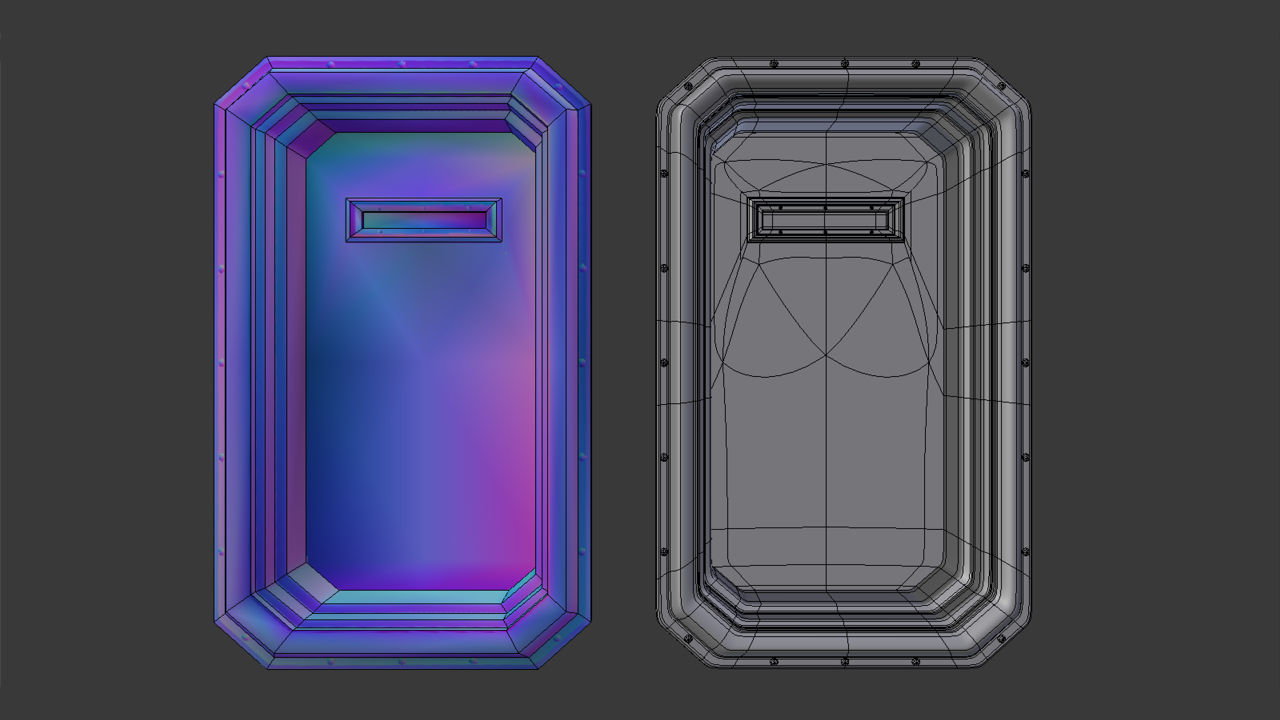
Before baking make sure to have both a LOW and HIGH resolution mesh available, both of which should occupy the same location, be the same size, have the same Origin points and be ‘fixed’ (shown side-by-side in the above for clarity – at render they will be co-located and sit atop each other. “Draw all Edges” is also active, found in “Object” Properties, to highlight structural or density differences between the two versions)
In addition, the low resolution mesh MUST be fully “UV Mapped” with an “Image” assigned using either ‘generated’ or ‘bitmap’ based data – the map itself acts as a guide within which image data is baked, the image as the ‘substrate’ or ‘canvas’ to which that is done.
Design note: the above assumes the bake process is just for the production of a Normal map independent of any Material(s) it might eventually be associated with: it can be generated without the need to assign a full Material to the mesh. If a Material is needed (because the resulting Normal map is to form part of a ‘live’ datablock immediately after baking) – with the low resolution mesh selected click the “Material” button in Properties. The panel that appears should be blank. If it is click “+ New” to generate a populated Material slot. Leave this as is and then click the “Texture” button. Again if an entry does not exist click “+ New” to create one. Here change “Type:” to “Image or Movie“, then in the “Image” sub-section click the “Browse Image to be linked” button (button with a landscape picture icon – don’t click “+ New” or “Open”). From the drop-down menu list that appears, the image previously generated and assigned to the mesh should be available, select it to assign to the Material making it ready for baking. Further information on setting up Materials can be found here.
To create the ‘image’, in the “UV/Image Editor” click the “Image” menu option in the Header then “New Image” to access the image properties popup (alternatively click the “+ New” button also visible in the Header). Set a “Name” (or leave the auto-generated value in place, usually “Untitled[.n]“), change the “Width:” and “Height:” as needed based on the shape and size of the mesh, the expected layout of the UV map (e.g. “1024” by “1024”), or the size of the image required. Set the ‘style‘ of image to be used selecting one of either “Color Grid“, “UV Grid” or “Blank” from the “Generated Type” selector, then click “OK” to confirm and generate. The new image will immediately appear in the UV/Image Editor occupying what was previously a blank “Texture Grid“.
Design note: the only significant difference between “Color Grid“, “UV Grid” and “Blank” is whether a pattern or a uniform (single) colour is displayed; the latter tends to make it easier to see the UV when unwrapping and editing, whereas the former make it easier to see distribution and relative image density across the mesh – ideally their respective patterns should be uniformly distributed, especially in areas immediately visible to the viewer/player. In addition, to aid the UV editing process the different image ‘types’ can be swapped back-and-forth to make the UV editing process easier – for example using “Blank” to see the initial UV map, then “UV Grid” to check distribution. To do this, in the UV/Image Editor click “View » Properties” to access the Image Properties. panel (or press “N” with the cursor over the active view), then click the “Color Grid“, “UV Grid” or “Blank” buttons as needed.

Generating a new Image that’s assigned directly to the UV without the use of Materials; the low-resolution mesh is shown in Edit mode to display the UV Map before texture application – the map is slightly distorted due to the default “Texture Space” (grid) being square (high resolution shown with “Draw all Edges” active for clarity and to highlight structural differences)
If the mesh has not yet been unwrapped, whilst selected press “Tab” to enter Edit Mode, “A” to select everything (or from the 3D View Header click “Select » (De)select All“) before finally pressing “U” and selecting “Unwrap” from the “UV Map” pop-up menu. This generates an initial map to which the previously created image can be assigned before then editing and marking the mesh with Seams for better Unwrap.
Design note: UV unwrapping is selection based process, only surfaces highlighted at unwrap generate a map to which an image can be assigned, else surfaces appear ‘white’ (no Material/UV Map) or ‘pink’ (missing Image). Once the initial map is generated it can be edited as normal using Seams to split the UV and lay it flat.
")
Shown in “UV Editing” layout (selected from “Choose Screen Layout” in the upper Header/Info bar), the objects initial UV is mapped to a square grid, the UV/Image Editors default “Texture Space” – this automatically readjusts itself one an image is associated with the mapped UV’s. Note also that as an image has yet to be assigned to the object it appears white in the 3D View
For that, whilst the mesh is still selected, in the UV/Image Editor click the “Browse Image to linked” button in the Header (icon displaying a ‘photograph’) and select the previously created image from the ‘browse’ list that emerges, assigning it to the UV map and the mesh (which will appear in the 3D View subject to being in “Texture” mode, “Alt+Z“). Once applied continue to edit the UV’s so they map to the image as needed – it’s important the low-poly object be fully unwrapped before continuing because the map itself, its shape and coverage, is used to guide the process, it acts as a template of sorts into which the RGB data from the high-resolution mesh is baked.
Design note: the image can be assigned before or after the UV map has been generated and edited, doing one or the other is largely a matter of preference. If done after however, some adjustment to the UV map may be necessary if the image used is not square (the texture grid is square so the UV map will expand when assigned to a wider image). To aid the general process editing the UV map, enabling “Snap to Pixels” helps by making sure mesh vertices align to texture pixels – with the entire mesh selected in Edit Mode to expose the UV’s, click “UV’s” then “Snap to Pixels” in the UV/Image Editor, then (optionally) with the entire UV selected make a minor “Scale” adjustment, “S“, to nudge individual vertices to the pixel.

Selecting the previously generated image in the UV/Image Editor to assign it to the initial UV map (shown contained within the default square “Texture Space” area – click the “Browse Image to be linked” button selecting the entry from the list (in this instance “Untitled“)

Make sure the low-poly mesh is fully UV unwrapped and has an Image assigned (a “Generated” image in the example shown above) before continuing (mesh shown in Edit Mode and selected to display the UV map and image in the UV/Image Editor using the “UV Editing” screen layout)
High-poly mesh preparation
The high-resolution mesh on the other hand needs little additional preparation other than ensuring it’s size/dimension, position and Origin match the low-resolution facsimile – it does not require materials, images or to be UV unwrapped. High-resolution meshes can be used with or without modifiers so it’s not strictly necessary the “Multires” or “Subdivision Surface” modifiers be applied to the mesh beforehand (click “Apply” within each Modifier panel). Mesh data can be presented in its original ‘quadratic’ form or optionally tessellated (triangulated), “Ctrl+T“, before baking. This is not absolutely necessary for the process to work however.
Design note: for super-high resolution meshes tessellation may not offer any significant advantage because there would be far more surface volume on the mesh than is available on the assigned image for a 1:1 surface/pixel correlation (the accuracy of the resulting Normal map relative to the data baked is defined by the size of the image mapped to the model – smaller images mean less pixel space available for baking which reduces the accuracy represented in detail and structure). Where it may be prudent to triangulate is in instances where the reference mesh is not suitably dense, which can increase the risk of bake errors where the render process has difficulty determining whether an un-split face is concave or convex, leading to incorrectly baked RGB values.

The high-resolution mesh (selected and shown with “Draw all lines” active) can be ‘sub-divided’ manually (i.e. subdivided through use of the “Subdivide” button in “Tools“) or assigning the “Subdivision Surface” or “Multires” modifier, either ‘fixed’ or ‘unfixed’ (the modifier properties being applied and ‘made real’) before being baked
Texture Bake
Once the mesh has been UV mapped and an image assigned click the “Render” Properties button (‘camera’ icon). Scroll down to the “Bake” subsection at the bottom of the panel and click the black triangle to the headings left to access its respective properties and options. Here change “Bake Type:” to “Normal” (“Bake Type: Normal“, displays “Full Render” by default) and activate “Selected to Active” by clicking the checkbox so Blender knows the Normal map is to be produced using the low/high resolution mesh pair.
Design note: when checking “Bake” settings it’s also prudent to have “Clear” set so the process essentially wipes the image and re-bakes the data ‘as new’ when re-baking after adjustments are made where needed. Further “Margin:” can be set to a higher value, i.e. “16 px“, to compensate for UV positions relative to each other where the resulting image is to be used with mipmaps; as mipmaps decrease in size, the distance between UV islands diminishes so a larger initial value is used to compensate for any subsequent loss of pixels due to image size reduction – this value does depend on the textures actual size, a 16px margin uses a significant amount of space on a 128 x 128 pixel image but very little on a 2048 x 2048 image. Adjust the “Margin:” value as appropriate.


Switch to “Render” Properties and scroll down to the very bottom to access the “Bake” systems options and settings (defaults shown first image above). Change “Bake Type:” to “Normal” and activate “Selected to Active” so Blender knows how the Normal map is to be generated. Note meshes are shown positioned as they should be for rendering, moved together so they occupy the same position on the grid, important for ‘like-for-like’ texture baking
Finally in the 3D View make sure to double-check the high-resolution mesh is selected FIRST and the low-resolution mesh LAST – the order is important – then click the button marked “Bake” to generate the map. A progress bar will appear in the “Info” header atop the application, disappearing upon process completion.
Design note: the order objects are selected ensures render takes place correctly; the low-resolution mesh, the item assigned the image, should always be the LAST item (multi) selected (“Shift+RMB“) else the process will error out.

Make sure the low-resolution mesh is selected LAST (should be active object) then click the “Bake” button to generate the Normal map – a progress bar appears in the “Info” header showing render status

The resulting Normal map baked to the image previously mapped to the low resolution mesh, which can now be saved and used as needed – mapped to an object for game use – note the image, once saved, will need to be re-normalised to remove the grey background and ensure it only contains normalised RGB colour values, else it may cause issues when used in-game (‘grey’ is not a normalised colour)
Save the Baked Texture
Once bake has finished the resulting Normal map will have appeared in the UV/Image Editor where it can then be saved. To do this from the UV/Image Editor Header click “Image » Save as Image” or “Image » Save a Copy“, either option opens the “File Browser“. Select a suitable image format from the “Save as Image” properties section bottom-left, preferably ‘loss-less’ such as “BMP” or “Targa RAW“. Browse to the location the file is to be saved, and then click the “Save as Image” button top-right. Blender will pause as the temporary bake data is written to file and then return to the previous view once done.
Design note: the difference between “Save as Image” and “Save a Copy” has the former save the baked data to a suitable format using the new file to over-ride whatever currently resides in the Material and mapped to the mesh. Whereas the latter will save a ‘copy’ of the same bake data leaving in place whatever is active until the main *.blend file is saved or reloaded – bake data is temporary in nature, as such will be lost when doing this (dumped into a temporary data/image buffer).

From the UV/Image Editor click “Image*” then “Save as Image” or “Save a Copy” to save the data in a usable format (the “*” appended to the “Image” menu option in the Header indicates generated data has not yet been saved, removed once that has been done)

In the “File Browser” that opens select a loss-less format to save the image to from the options dialogue lower-left, “BMP” or “Targa RAW” for example, browse to a location to save the file, then click “Save as Image” top-right. Blender will then return to the previous screen once done
Broken renders
During the bake process it’s not uncommon for renders to exhibit artefacts as a result of disparities between the high and low resolution meshes and the origin point from which rays used to analyse mesh are cast; if the allowance is insufficient the end result is usually some form of image corruption.

The difference between the Low and High resolution meshes needs to be consider for baking else the render process results in images being corrupt or exhibiting other forms of visual aberration, essentially making the Normal map unusable
In other words when making low/high resolution mesh pairings for Normal map baking, it’s expected there will be some degree of co-planar surfacing, overlaps or protrusions – rivets, screws and other features can sit exactly at, above, or below, the low-poly mesh such that when the bake process comes across these types of structures they may be inadvertently clipped or improperly rendered because the point from which bake is initiated is too close to a surface. The result is typically a broken or incomplete rendering of structure.
Using the default values to bake Normal maps may cause image artefacts (shown in the above as pattern interference, especially noticeable in the flat windowed area to the right) due to the origin point of the ‘ray’ used to determine structure being too close to surfaces; if the tolerance is too low features above or below might not then bake correctly because they’re essentially clipped from consideration
To compensate for this disparity the distance between surfaces and the origin point of the ray-cast can be increased or decreased by adjusting “Distance:” and “Bias:“; although each performs a particular function, in practice higher values mean more of the mesh can be captured for rendering. To make adjustments; in “Bake” Properties click either “Distance:“, “Bias:“, or both in turn, and type a suitable value depending on the significance of detailing that needs to be considered, then re-bake to rebuild the Normal map.
Design note: as a general rule-of-thumb the distance used tends to be reflective of the difference between the lowest point of the low-poly structure, meaning both “Distance” and “Bias” equal “0”, and the height/depth of features needing to be captured on the high-resolution mesh, meaning “Distance” and “Bias” equal a value that allows the entire structure of both meshes to be fully evaluated. Although this can be determined by measuring the features in question, both ‘Distance’ and ‘Bias’ values are represented in Blenders Units, some experimentation may be necessary to find the happy median – it should not be so low as to fail at preventing artefacts, but also not so high as to cause similar issues in reverse. Distance and Bias are also relative to mesh size and scale so higher values may be necessary for large objects.

To mitigate issues of bad or poor rendering, “Bias” and “Distance” values can be increased to include more geometry in the bake process, essentially expanding the area captured, compensating the clipping that might inadvertently occur due to the proximity of both meshes to each other and the ‘ray’ origin used to calculate and render down those same structures

With “Distance:” and/or “Bias:” set to appropriate (higher) values a cleaner bake is possible because all the necessary mesh structure is being fully captured for processing
Baking and Anti-Aliasing
As with most forms of baking, “Aliasing” presents a particular problem because its reliant upon the ability of the rendering system to interpolate and ‘anti‘ aliase pixel data, and the resolution of the image being baked to. If one or both are insufficient the resulting bake exhibits ‘aliasing’ or significant pixelation that often manifests as visible ‘stepping’ or ‘jagged’ edges around non-axial or non-perpendicular details and structures (e.g. rivets, screws and other curved details). In other words the bake process is not inferring or averaging pixel data with respect to generating clean edges around structural features that don’t run along the horizontal or vertical axis.
Design note: aliasing issues tend to occur when image data is not correctly, or fully, interpolated when baked. In other words the render process is analysing structural data at at face value, i.e. as it appears to the renderer absent, or with minimal, interpreted averaging between pixels to fill in the gaps, the ‘anti‘ in “anti-aliasing“.

Shown in “UV Editing” layout for clarity, Normal maps baked without “Anti-Aliasing” often exhibit ‘jaggies’, the ‘stepped’ or pixilated appearance of edges around non-perpendicular structures (that don’t run along the horizontal or vertical axes)
In practice, absent proper “Anti-Aliasing” or “Sampling” options, the solution is to edit the Normal map outside Blender, manually painting in what’s missing using a third-party image editing application like Photoshop, GIMP, PhotoPaint etc. (or whatever image/photo editing software is available). Alternatively the map can be baked larger than needed then down-sized, again using a photo-editor, taking advantage of the indirect anti-aliasing that occurs when images are re-sized. Still further the map can be left in its raw state relying instead on anti-aliasing being performed at run-time when image data is re-sampled and re-drawn to differing sizes on screen.
Design note: when manually editing Normal maps through painting it’s often better to split and edit the channels individually, correcting each of the ‘R’ (red), ‘G’ (green) and ‘B’ (blue) colour channels separately rather than as a combined RGB image – channels only contain saturation data pertaining to the colour they represent, i.e. “0%” or “0” saturation, often displayed as black, represents no channel colour, whereas “100%” or “255” saturation represents full channel colour, a total range of a single colour from ‘black’ to ‘full’ colour – 0% to 100%, or 0 to 255 saturation. Overall this makes it less likely colour aberrations will be introduced to the image, although care still needs to be taken to match edited tones exactly else the end result is a malformed Normalised surface in-game.


Shown in “UV Editing” layout for clarity, the objects Normal map is baked to a 256×128, 2048×1024 and 4096×2048 texture respectively, each of which has a differing affect on rivet detail clarity – in essence larger images mean fine details can be better defined as more pixel data is available for use, distributing aliasing across more data and in effect pseudo ‘anti-aliasing’ the image
Mesh Smoothing & Normal Maps
When baking Normal maps using the “Selected to Active” approach, “Mesh Smoothing” is determined not by edge or face splits on the low-poly mesh but instead on the high-poly using “Control Loops” or other types of “Control Structures“. Typically extra geometry placed strategically to change the density of a feature or features, it’s this data which when baked as biased RGB Normalised colours, informs the behaviour of smoothing on the low-poly mesh with respect to the high-poly geometry it directly represents. In other words meshes are typically smoothed based on the continuity and colour of Normalised pixels across a UV mapped surface, not the surface structure itself – modification to the latter tends to have a detrimental effect because it interferes with the former.


Image-top shows how mesh density changes the way structure can be seen to curve and respond to lighting/shading. In this way hard (1) or soft edges and curves (2) can be controlled by changing the mesh which in turn, Image-bottom, is then represented in RGB as similarly hard (1) or soft edges or curves (2), or a combination (3), thus controlling the way smoothing behaves
What this means in practice is that the conditions for baking textures to a low-poly object, and using such objects in-game differ; during bake, the low-poly mesh will typically have minimal smoothing in place, if at all, because edges, corners, crevices, bevels and so are defined by the high-resolution mesh; whereas in-game some smoothing may be necessary to augment a structure, i.e. splitting unseen faces to aid the appearance of others that are.

Shown in “UV Editing” layout for clarity, the low-poly mesh is shown with its left side set up to use uniform smoothing, and edges marked as “Sharp” on the right. The baked Normal map, shown in the UV/Image Editor (left side of Blender), displays the result and what affect smoothing, or not, has on Normal maps – the difference can be significant

Displayed in “Texture” mode (again shown using “UV Editing” layout) the Normal map affects the meshes appearance quite significantly – in-game this has a similar affect often causing the completed model to exhibit surface problems

Expanded view (shown full screen in the UV/Image Editor for clarity) of the same baked Normal map with uniformly smoothed surfaces on the left of each section and edge splits on right; the difference can be quite significant depending on the type of object baked so special care should be given to Baking where ‘Smoothing’ needs to be used
With this in mind special attention should be given to the use of Smoothing and Smooth Group like enhancements so they don’t break Normals, which for all intents and purposes means “Mesh Smoothing“, “Smooth Groups” or “Hard Edges” are to be avoided, certainly for baking purposes. In other words the low resolution mesh should be assigned a single ‘smoothing’ value or group, or where they are needed it should be done in a way that doesn’t detract from the use of Normal maps, i.e. edges or faces marked in a way that’s not immediately obvious to the viewer.


Smoothing can be used but care should to be taken as to the effect doing so has on the resulting Normal map (note also consideration should be given to aliasing issues where hard edges appear – another incidental reason to avoid using “Mesh Smoothing” if at all possible)
Renormalising Normal maps (renormalisation)
When Bake completes Blender displays non-normalised areas of the map in the UV/Image Editor as a flat uniform grey colour. When the map is subsequently saved it may included these depending on the completeness of what was rendered. If this is the case the entire image will need to be “re-normalised” to convert non-normalised colours to valid normalised RGB values. This is important because Normal maps should only contain RGB normalised values (each “R“, “G” and “B” using only “0 » 255” saturation), any that are not will result in an unusable Normal map (subject to engine tolerance).

Baked Normal maps may include invalid colours which need to be removed before the map can be used in-game, else they can cause the appearance of aberrations and other types of malformed surface, if not make the map unusable (shown in Corel PhotoPaint)
The simplest way to re-normalise an image is to filter it using a tool or plugin designed specifically for that purpose (subject to availability for the application used). If one is not available some manual image editing is necessary to correct the problem. To do this open the image and, if not already masked as a result of the bake process in Blender, select all the grey areas, creating a mask or layer from the selection. Once done simply flood-filling the areas, masks or layers with the appropriate normalised colour, commonly this will be a ‘flat’ or ‘mid-tone’ value of RGB “127, 127, 255” or “128, 128, 255” depending on the engine used.


Before use Normal maps need to be “Re-normalised” wherever they contain none invalid RGB colours. How this is done varies on tool or filter availability but can be done manually by masking of aberrant areas and flood-filling them with an appropriate ‘mid-tone’ normalised colour (“127, 127, 255” or “128, 128, 255” depending on the game engine used)
Summary
The following is a basic summary of the process as a quick check-list for use.
- Make sure both meshes are the same size and at the same location.
- UV map low-poly mesh and assign an Image (with or without Material).
- High resolution mesh can have Subdivision or Multires modifiers active.
- Set “Bake” options “Normal” and “Active to Selected“.
- Click the “Bake” button to generate Normal map.
- Save the result to a loss-less format e.g. *.tga.
Conclusion
Blenders internal render engine (“Blender Internal”) has long been used to bake various types of image map for meshes using the “Texture Bake” system. Although there are one or two disadvantages to Blender Render (some of which are mentioned above) its still a viable option providing consideration be given beforehand to issues that might occur. One important point to note however is that Blender Internal is no longer being actively developed or support beyond critical bug fixes as Blender Foundation focus is on Cycles Render.
Video
The video below shows the basic procedure discussed above.

