Make Normal Maps From Images (+Video)
Normal maps are best generated through ‘texture baking’, i.e. the structure of a high-resolution mesh is ‘baked’, or rendered down, to an image mapped to a low detail facsimile. For large projects this can be incredibly time consuming, and for objects the player does not directly interact with, is an inefficient use of time. To work around this it’s possible to produce Normal maps of reasonable quality from images specifically designed for the purpose, i.e. their being converted to Normal maps.
Download: Katsbits – Scaffold Example (c. 600 KB | *.blend, *.tga).
The following tutorial on making Normal maps from images explains the process of making an image, a heightTemplate, of a simple girder truss support specifically for Normal map filtering and conversion (which differs from using photographs). Also discussed are alpha masks and their use in removing specific areas of a texture. A basic understanding of image editing software is required.
Design note: images shown below are a 128 x 128 section of a larger texture – 512 H x 128 W pixels.
White is Height, Black is Back
The basic principle behind making an image specifically for conversion to a Normal map can be summarised by the following simple ‘rule’; "white is height, black is back". Normal map converters don’t understand ‘context’ they’re not able to determine what a given tone of black « » grey « » white is meant to represent from a height and depth perspective; is a dark colour actual depth or just shadow or dark paint. To this end the aforementioned rule forms the basis upon which all Normal map templates should be made, that ‘white’ represent surfaces closest the viewer whilst are ‘black’ are farthest. In other words; ‘white’ tones protrude, ‘black’ recede. In this way pseudo three-dimensional structures can be represented simply from a collection of greyscale tones.
Design note: typically the image created for conversion comprises solely of greyscale tones. This can be as an 8 bit "greyscale" image (single 8 bit channel), meaning 256 tonal variations are available, or as a standard 24 bit "RGB" image with 16+ million..
Image Layout
Before continuing consideration should be given to how the final texture is to be used. In a BSP or brushed-based environment, Radiant, UnreadEd or other ‘grid-based’ editor for example, structural element within the image might need to allow for the snap increments used by those environments to ensure world volumes are of a ‘regular’ shape or format – blocks that are 8x16x32 units for instance. In practice this might mean the core image being specifically designed so it can be used in a number of ways; in making a truss-support, the whole or parts therein, could be used to differing affect.
Design note: where possible it’s preferable to cater to a single image having multiple uses than one that doesn’t, which is essentially a form of optimisation or efficiency strategy – a 512 x 512 image could be used in its entirety across an object or as a 32 x 512 section; in both instances the same texture is loaded into memory rather than two separate textures, one per usage (which might also then mean 2, 4 or 8 additional assets being loaded depending on whether specular, gloss, alpha masks and other image ‘types’ are used as part of the material set).
Initial Layer For Size & Scale
With the above in mind, to set the initial size and scale of the girder/support, two parallel objects are placed establishing the distance between each other and the thickness of the beams main support struts (32 pixels wide in this instance). Overall however, the beam occupies the entire width of the image. If the image is to tile left/right (and up/down) ensure these first objects butt up to the outer edges of the document otherwise the final texture won’t tile properly, which is often revealed by a line emphasised by the Normal map.
Design note: the initial thickness of the upright segments should be reflective of the point made in the previous section; each might be 32 pixels wide, a measurement that can be comfortably used 1:0.5, 1:1 or 1:2 with a brush volume, structure or object being 32 ‘units’ wide, i.e. 1 pixel per in-game unit. The tone used for this initial stage should trend towards being mid-grey as this allows for a certain amount of leeway in terms of height and depth (the image is starting from a mid-point).

Initial uprights that establish the general layout of the texture
Depth Using Layers
With the initial layer in place the next step is to start building ‘depth’. Keeping in mind that lighter tones equate to ‘height’ the next shapes will be lighter in tone – because this essentially sits above the previous darker tone the resulting surface will be raised once its passed through the Normal map conversion tool. With this in mind make sure when placing the new objects that at least 1 pixel from the underlying layer is visible – if the base layer objects are 32 pixels wide, the new layer should be 31 pixels.
Design note: the width of the upright struts is determined by the base layer, which is 32 pixels wide – detailing added after the fact can be any size relative to their function largely as detailing.

Second layer of lighter colour to add depth
Cross Members
The first layer of the cross-member supports use the same grey tone as the previous layer, and as they sit above the 1 pixel inner edge, this will result in a slight emboss giving the impression they are pressed from, or welded to, the main struts. To create ‘angled’ elements draw a line or block, making sure to over-extend top and bottom to compensate for the additional distance needing to be covered by rotating a certain number of degrees – in this case 45°. Depending on the design once one segment is position it can then be duplicated and mirrored or rotated to other places.
Design note: rotating objects will introduce some degree of "Aliasing", the noticeable ‘pixel stepping’ artefact often seen running along the edges of angled objects which, depending on the size of the image, may be significant because anti-aliasing – the interpolation of pixels to smooth edges – can’t be clearly defined (usually due to lack of available pixel data to do this). It is possible to mitigate using blurring and feathering but may result in an edge that’s too soft. This issue is one of the reasons why it’s preferable to model and then bake Normal maps using meshes as those systems have better sampling and interpolation algorithms.

Cross-beams added the same tone as the previous layer which result in their eventually appearing to be pressed from the structure (press or formed metal sheeting)
Adding More More Height
To make the uprights more distinctive than the cross-members, another slightly thinner layer is added, filled with a still lighter tone; because underlying darker tones are exposed at the edges the result will be more height present in the Normal map. Again for tiling, make sure both sides are equal so mirror or copy/paste across to match both sides together.
Design note: for height increments to be properly converted to Normal’s there must be at least a single pixel along an outside edge of an element; it’s the tonal difference between layers that primarily determines the overall height of an element – one pixel exposed across several layers of differing tonal range will be interpreted as a relatively smooth transition bottom to top, whereas a lighter colour over a darker without mid-tones creates an abrupt change that’s interpreted with greater significance resulting in a much harder height change in the Normal map.


To give the general structure more depth/height two additional layers are placed, one to replicate the main structure, the other just the uprights; both being two or three pixels narrower overall will create a ‘bevel’ in the final Normal map
Adding Fine Details
With the basic structure in place detailing can then be added. Depending on the ‘look’ required it’s important to keep in mind that because the image being built is to be used to generate a normal map, only structural data is needed, i.e. the design should relate to what the object is rather than what it’s made from. In other words surface information (‘rusty steel’ for example) does not specifically need to be included at this point. Structures should then, just related to the object descriptively; lighter or darker tones used to highlight or recess certain areas – darker shapes added to give the impression of reinforcement shaping typical of pressed metal for example.
Design note: subject to the physical size of the texture being made, wherever possible avoid including isolated features smaller than a single pixel in height, width or both – with the exception of edges belonging to larger structures – as tiny details don’t provide enough structural data to be converted meaningfully; to properly convert a single pixel the process has to interpolate additional pixels around the object taking up space. In practice this means care should be taken when placing rivets, screws, trims and other detailing.


Adding detailing using various shapes and overlaps to create indentation or embossing’s in the final Normal map – avoid where possible making individual or isolated details smaller than a few pixels as depth/height can only be produced adding more colours to the map which may cause issues elsewhere
Creating Cut-Out Areas
Once the main structure is complete it can be further detailed with the addition of cutouts. In the example shown opposite these are simple edge modification removing what might be considered extraneous materials that would otherwise add weight but not strength to the support, that can be any shape or form, or be in any position. Again subject to what the object is supposed to be, uniformity is key – this ensures the object tiles correctly and has multiple applications. Opposite then, the cut-outs are drawn as squares with rounded corners and then rotated to match the angle of the cross-members (45°) before being placed in a way that ‘cuts’ into the cross-beams – because these are cut-outs, material removal, they need to be black where the shape is to affect the entire structure, or matching the tone of a specific layer – cutting a section from an upper segment means filling the shape with the tone used for a lower.
Design note: fixed guidelines or using grid-snapping aids alignment of objects when doing this type of manipulation. Again because elements are being rotated off-axis care should be taken to address aliasing as it happens.

Shapes can be cut from others based on the tone, by match that of a lower layer sections can be removed from those above – black is used to match the background and ‘cut’ through the entire section
Final Steps & Image Template ‘Prepping’
The final step before passing the template through a Normal map converter/filter is to flood fill the background, black as in this instance, or as dark a tone as possible relative to the overall texture, to achieve the depth required compared to the rest of the image (whichever tone is used it will become the ‘baseline’ tone against which others are defined in relation to height upwards from the background fill). Once done the image is basically complete and ready to be converted.
Design note: how certain aspects of the process are performed depends on personal preference and the organisation or availability of tools appropriate for the job at hand – it might be as simple as flood-filling the actual background of the image, or alternatively a pre-positioned layer/object.

The background colour should be the darkest tone before conversion as other, lighter tones calculated relative to it – its essentially the ‘bottom’ of the structure
Converting to Normal map (Photoshop & GIMP etc.)
Once complete the image can be converted to a Normal map. This can be done directly within the photo or image editing application used to make the image with a filter or plug-in, or indirectly by saving and opening, or copy and pasting, the image into a third-party program. Either/or depends largely on the complexity and options provided and/or needed for/during conversion.
Design note: before processing ensure the document contains greyscale tonal values only; flatten the image then either ‘desaturate’ to remove non-grey colours and tones, or convert to 8 bit then back to 24 bit before filtering or saving the file.
For the former, using a filter or plug-in, whilst the document is still open in the image-editor (e.g. Photoshop, GIMP, PhotoPaint etc.) simply flattened or collapsed it so all the individual layers or objects are combined with the background or base-layer, and then run through the programs Normal map filter or plug-in.
Design note: the image generally needs to be flattened to ensure the process applies to the entire image rather than a section or the active selection.
For the latter, using a third-party converter, flatten the file and "Save As…" to an uncompressed or loss-less compression format such as *.bmp (bitmap), *.tga (Targa) or *.tif (TIFF). Once done open the file into the third-party Normal map converter program and process. In both instance, using a filter and third-party program, the resulting image should then be saves primarily as an uncompressed or loss-less compressed 24 bit RGB image (again *.tga, *.bmp or *.tif).
Design note: preference should be given to saving the resulting Normal map as a raw or uncompressed image so clean source data is available for further editing where needed, or re-saving to multiple formats or using different levels of compression, i.e. to *.dds (DDS – Direct Draw Surfaces).
")
The final Normal map converted from the image (converted using Njob, shown in Photopaint for clarity)
Alpha Masks & Normal Maps
Alpha masks (alpha channels) are not generally added to Normal maps for ‘masking’ purposes, they are instead usually included as part of the Diffuse image, which then requires a set of game specific Material instructions to actually pull the masked area from display.
Design note: depending on the material complexity needed by a given games rendering engine, only one image might need to have the actual alpha-mask, others can then utilise the same channel for different effects – gloss, specular, bump etc., for example Blender Game Engine only needs and alpha-channel included with in the Diffuse image to affect all underlying stages (and images) within a Material.

Masked area shown highlighted ‘red’
Having said this however, if a mask is to be included there are a number of ways this can be done depending on the tools and options to hand within the photo or image-editing application; the simplest might be to re-open the working file and ‘paint-select‘ the black tone of the background, or the light tones of the structure (whichever is easier to select based on tonal dominance). Or similarly use a ‘magic-wand‘ to auto-select well defined areas.
Design note: in all instances selection will likely need to be a ‘multi-selection’, i.e. select an area, hold "Shift", select another area to add to previous and so on.
Once the necessary area is masked, applying it to the Normal map can be done in several ways, primarily either; copy/paste the Normal map image over the top of the working file and merge; or save the masked area to another file ("girder_mask" for example) which can then ‘loaded in on top of the Normal map image specifically as a mask.
Design note: when saving/exporting a mask from a working file it may be possible to save it as an actual mask or a plain image, the difference generally relates to how each is used and the types of tool available, as well as being subject to personal preference.
Once the mask is created the resulting image can then be saved or exported as a 32 bit *.tga, *.dds, or other game supported format that allows the inclusion of masks/alpha-channels.
Design note: in this context a "32 bit image" is actually a 24 bit "RGB" file with an extra 8 bit channel used for the alpha ("A"), i.e. 24 + 8 = 32, an "RGB+A" image, It should not be mistaken for being a ‘true’ 32 bit CMYK image, the type usually associated with printed materials.
")
Masked area (white) assigned to the Normal map (shown in Photopaint for clarity)
Getting Normal Maps into Game
The specifics of getting the Normal map into a game won’t be covered here as each editing or development environment have differing requirements for doing that. Suffice to say however, that a special ‘shader’ or ‘material’ will need to be written that instructs the engine what images are being used and how to use them, alpha included; a typical shader for idtech 4 might be similar to the following (below) for example. In all instances however, each image will be referenced directly based on a path to their physical location as well as having an associated ‘property’ that affects their appearance in game.
//steel girder
textures/supports/girder
{
qer_editorimage textures/supports/5_v2fb_diffuse.tga
// noshadows
twoSided
{
blend bumpmap map addnormals( textures/supports/5_v2_local.tga,
heightmap( textures/supports/5_v2fb_h.tga, 4 ) )
}
{
blend diffusemap map textures/supports/5_v2fb_diffuse.tga
alphaTest 0.5
}
{
blend specularmap map textures/supports/5_v2fb_s.tga
}
}
")
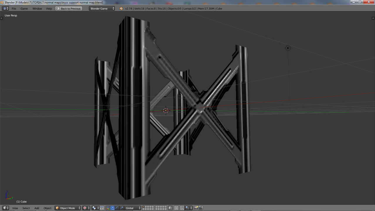
Not quite into game but shown assigned to a simple mesh in Blender Game Engine render mode with GLSL material shading active which approximates the way Normal maps are displayed in games
Normal Maps & Shadows
A quick note on shadows. On their own the structures described by Normal maps don’t generally cast shadows, they ‘shade’ – maps highlight and darken relative to lights but do not cast shadows across their own surfaces, the do not "self-shadow" in other words. For Normal maps to cast shadows additional texture data or Material properties referencing specific graphics functions are typically needed which alter what’s drawn to screen at the pixel level (pixel shader modifications). In other words, Normal maps pertain to surface rather than structural so meshes should be constructed accordingly.
Normal maps shade rather than cast shadows unless modified using special material properties
RGB Orientation
As discussed above the colours displayed in a Normal map determine the orientation of a pixel when displayed on-screen – "blue" usually represents up/down (depth), "green" left/right, "red" top/bottom. However, the red and green channels can be flipped depending on the peculiarities of a given game engine (or the tools used to convert the image to Normal map) which often result in materials appearing inverted in-game (generally noticeable because surface shading reverses – dark areas face towards light instead of away from it). The fix for this is to re-open the Normal map in an image-editor and ‘invert’ either the red or green channel as needed (rarely do both need to be inverted or the blue need to be touched).


Inverting the ‘green’ channel to corrected an inverted Normal map where either the ‘red’ or ‘green’ channel data makes the map appear backwards – inverting fixes this (top: before, bottom: after)
Conclusion
Normal maps should ideally be generated from mesh data but where that is impractical or overly time-consuming a properly prepared image can do the job reasonably. There are some limitations however, and where possible preference should be given to baking meshes. This obviously necessitates some forethought to organise production so incidental textures (ones the player doesn’t get too close to) are largely the ones converted to Normal maps from images.
")
Render of girder with all layers in place shown in idTech 4 – note the Normal map displays shading where recesses are located but not shadows that might otherwise be visible where an element of the Normal map would physically protrude from a surface (the centre support point for example)
Video
The following shows the basic process discussed above of making a similar truss-support structure from start to finish before testing in Blender Game Engine render mode with GLSL material shading active.
Overview making a Normal map of a girder (similar to the above but not the same) from a similar type of greyscale ‘template’ created in Corel PhotoPaint and then passed through Njob for conversion to normal.

