Modelling A (Quake III) Map In Blender
Although the following tutorial discusses making a Quake 3 level using Blender 3D, kat1024 in this instance, the techniques involved can be used where modelling rather than ‘building’ a level is required. The process is ostensibly applicable to game engines and game design with BSP style geometrical requirements, i.e., idTech, UDK etc.
Download: Katsbits – Kat1024 Source File (c. 6 MB | *.map, *.ase, *.tga).
The tutorial is meant to serve as a general guide rather than a step by step ‘how to’, and in doing so will cover the general principles level designers using Blender particularly, need to keep in mind when modelling a *.map in a 3D application rather than building it using brush based volumes typical or a dedicated BSP level editor such as GtkRadiant and its variants. Also discussed briefly is AlphaMod blending as applicable to *.ASE models.
The information below is relative to Blender 3D but the general principles apply to all 3D modelling applications.
Further Reading: for more detailed explanation on making maps or levels using Blender or other 3D Application read "Making a Simple Level". Note also that the below discusses modelling the level, i.e. exporting a series of ASE (or other format) static meshes, rather than constructing the map from mesh primitives (see aforementioned link).
The End..!
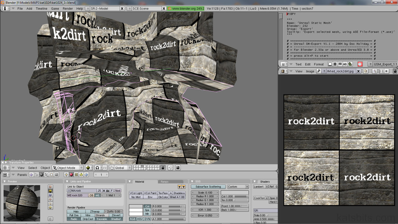
A good place to start. The image below shows a screen shot from a current sample map, kat1024 – ‘little rock’, that uses the principles discussed in this walk through. It’s an example of the kind of thing that can be done with a little bit of thought and is something that works particularly well with ‘organic’ shapes and themes; rocks, terrain’s etc. although the actual method of using models to create maps is applicable to just about any type of subject matter or theme you can think of.

The overall structure shown in the shot above is a model created and textured in Blender 3D
How Did kat1024 Come About?
The project linked to above (kat1024) started out with the intention of it being a Doom 3 multi player map. As a map for Doom 3 it needed a new rock texture so that was done; the texture itself was build as a high resolution model in Blender3D and then bump mapped (renderbumpflat’d) with the various necessary layers added to that (diffuse, specular and height).
Whilst looking at the new artwork it was realised a rock texture set for Quake 3 hadn’t been released for a while so the various ‘Doom 3’ layers were used to essentially create a ‘Quake 3’ version, one of which this map uses.
Rather than struggle with the layout and brushwork building in D3Edit I thought it’d quicker and simpler to block out a map in GtkRadiant which is faster to use in many respects. As per usual in doing this, mud fell from the proverbial eyes and a Quake 3 map was realised.
How does that relate to building a map in a 3D application? Read on…
Exporting & Using A Brush Template
Depending on what game the map is for you need to find a way to export a ‘template’ of the map layout into a 3D app irrespective as to whether this is a box or a complex multi room map doesn’t matter at this point and for Doom 3 this is relatively easy with Doom3Edit, just select the brushwork you need and use the selection > export to OBJ option in the main menu. This will export everything selected to and OBJ mesh that can be imported into just about any modelling app.
For Quake 3 there’s an extra step or two involved. You’ll need to use Q3map2 to convert a compiled BSP of the layout into an ASE model. From there you can either import that into another 3D app or if not a format converter will need to be found to get the ASE into a format your particular 3D app understands and can import. If you can’t find anything try using LEET by Bert Peers [local], it will import *.map files and then export them to *.DXF, *.3DS or *.ASE (although this isn’t fully operational you should be able to get an ASE mesh out).
Design note: in both instances above it’s best to strip out any game related entities and have just the raw brushwork present. Ideally you’ll need to texture the faces of the brushwork you want kept during export as caulk is ignored, a map covered in caulk exports, you guessed it, nothing.
The sample map above was made by texturing only the inner faces of a 1024 brushwork box in Doom3Edit and exported to an *.OBJ file. You could also do a similar thing as mentioned above using GtkRadiant and Q3map2 by compiling the map to ASE and opening that directly into a 3D app. If not the ASE can always be convert to OBJ using any number of ‘free’ 3D file converters floating around on the Internet.
Design note: although in this case a brushwork ‘template’ was used, a 1024 box, it’s not entirely necessary. However, it is worth considering because it allows you greater control over optimising what gets draw in game. When you put that model back into the map it sits over the top of the initial brushwork template and because of this the brushwork forms the physical structure and boundaries used by the map compiler to control VIS[ibility]. Without this, and depending on the model/brushwork, you may have a map on your hands that runs incredibly slow because the whole thing is being drawn all at the same time in game.
Related to this for bigger models / maps, is the need to split the mesh up into sections that follow the general layout of the templates blocked out brushwork. Models are not ‘optimised’ by default (polygon backface removal [culled]), so in a similar fashion to the above, the whole object will get drawn in one instance. To get round this the object has to be broken into smaller more ‘manageable’ chunks which are less taxing on the game engine to render.
We’ve now got a 1024 box mesh created using D3Edit to export an OBJ file. This is then imported into Blender where the rest of the work is done. Everything to do with the terrain mesh itself is done from here on in inside Blender3D.
How you actually build the model from here on in is up to you and the knowledge you have of the 3D application your using. Traditionally modelling starts with an isolated primitive – a ‘box’ or ‘cylinder’ for example – but you could just as easily use the template mesh created earlier, it acts as a very useful guide in a number of ways, setting both the bounds of the geometry and as a starting point to physically manipulate.
Design note: it’s worth pointing out here that it’s best to work in ‘quads’; this may mean the imported template model needs converting from a ‘tris’ (triangle) based mesh to a ‘quad’ (quadratic) based one. How this is done will vary from app to app but you’ll need to keep an eye on odd formations when you do this (for Blender see this tutorial for more info) as it’s often the case that certain triangle relationships make the conversion connect the wrong polygons resulting in ‘warped’ quads.
There is a reason for doing this; it make editing the mesh much easier. Leaving the polygons as triangles means you’re restricted in terms of how easy it is to edit, cut or shape multiple polygons. It also helps with the optimisation’s that will take place towards the final stages of the models creation; it’s easier to work from some semblance of ‘order’, which quads tend to create, than it is to work with triangle based ‘disorder’.
Waste Not, Want Not, Old Models With A New Purpose
The shot below shows what the sample map was created from; an unfinished wall prefab model test. This was modeled from a basic ‘box’ primitive, cut and shaped into the form shown below. It has some nice over hangs and undercuts which would make an interesting map, so that’s what was done.

The initial unfinished prefab used as a basis for the map, created as always in Blender 3D
If you hadn’t yet brought in the template, now is a good time to do so as everything will be built relative to that, it’s what gives the model it’s physically characteristics in terms of the layout of the mesh.
Design notes : as mentioned above, how you get to this point depends on how you model, in this particular instance this was a piece of ‘junk’ that could be put to better use. Just as the model converted brushwork template is used as a guide for the overall dimensions and layout of the map, so to does the unfinished object, it just creates a good starting point from which to work.
So using the unfinished prefab object in the shot above as a base I just kept the general theme and layout – you can see in the shot above the ‘strips’ or ‘tiers’ created by the deep cuts in the rock face – and then extruded the polygons out and around the template box guide, just keep in mind some basic contours so it at least you have some sort of interesting profile (from the top down view). It’s basic layout at this point so no cut always and hidy-holes just yet.

Basic layout extruded from the unfinished prefab
Adding Features To The Modelled Mesh
Once the mesh is at this point where you can see what going on, shapes and areas start to show potential for various ‘features’; the map could do with an inner ‘cave’ like area for instance so you basically look at the mesh and see where you could place that.

Features added to the mesh
Originally the inner cave was going to have some stone ‘steps’ but it was decided against as there wasn’t really enough room for them; the height to length ratio was to steep, so they were taken out to clear the space and open it up. It’s then just a question of playing with the mesh, pushing, pulling, deleting bits to create something with a little bit of interest.
Personal Log – stardate 22-45-99.05 : I’m very bad at game play specific maps by the way BUT an interesting thing about building a mesh (map) this way is that the game play generally ‘flows’ or ‘grows’ from the mesh in what I feel is a more ‘natural’ and ‘organic’ way, which is in tune with the visual’s of the mesh, rather than the other way around – I find it very difficult to lay down a game play ‘path’ and then build a map up around that – which is the way professional level designers do it.
This does mean that you may find yourself going back and forth fine tuning things in relation to the game play of the original brushwork template. modelling a map isn’t necessarily ‘quicker’.
Arranging The Models UVW Maps
So the mesh is finished and it needs texturing. The default UVW wrap for an object like this creates too much of a mess because of the unusual shapes it has, textures are pointing in all sorts of directions so that means looking at the mesh object and deciding on a ‘directional projection’ (‘DP’ – the flow of the grain the rock textures takes) for the UVW map. The mesh needs to be studied to find a good way of allowing the UVW map. to be broken up into smaller more manageable chunks that take into account the best DP. The good thing is that this particular mesh almost lends itself to being split up with natural divisions.
Incidentally this can generally be done in two ways;
- physical splits – the polygons are physically detached into more manageable sub-meshes and then UVW mapped.
- virtual splits – select certain polygons and UVW those as they’re selected, creating a ‘virtual’ split of the mesh.
It’s preferable to use the former but can prove tricky to match the UVW coordinates on each section so you get a smooth texture flow. I chose that latter; virtual splits. So with this in mind the whole map is UVW mapped. (just to get it down and dirty) and split into UVW sections in the UVW map. tool window (see below). At this stage all that matters is that they’re aren’t any holes (‘missing’ or ‘miss-mapped’ polygons) in the UVW mapped. sections.

UVW map. as applied in Blender using LSCM

Mesh split into corresponding sections (approximate) to match UVW’s
Once this is done it’ll free you up to just concentrate on getting the relative sizing right for each section. It’s worth noting here that you *always* get miss-aligned textures and you can never match UVW maps up edge to edge, the mesh geometry makes that impossible (obviously this depends on the mesh itself). What you end up doing is more akin to ‘damage limitation’; doing the best with what you’ve got.!
Exporting The Models To ASE
So the UVW map. is done, the texture is approx. the same resolution and same orientation over the whole mesh which means it’s ready for export. If you want to leave the mesh ‘as-is’ it’s then just a question of exporting from Blender to ASE using the USMase-exporter or the new script by goofos. It’s a good idea to initially export the mesh as one object like this to give you a ‘final’ version to work with inside the caulk box back in Radiant/GtkRadiant, you’ll be able to check that the positioning and relative sizing is OK. Doing this now means you can tweak the mesh and go back and forth between the two to make sure it’s doing what you want without to much fiddling with numerous mesh sections you may have it you cut it up.
Design notes: it’s at this point that the original brushwork template created in the game editor comes back into play. If you’ve done everything correctly, when you open the model in the editor it should sit exactly on top of this brushwork template, which now provides a structural ‘backbone’ to the map allowing it to be compiled without ‘leaks’. Incidentally the brushwork can now re-textured in caulk so you don’t get any z-fighting issues where model and brush surfaces occupy the same plane/surface.
AlphaMOD Texture Blending & ASE Models
Next comes the fun part… which I didn’t know you could do until I read a forum topic a fellow mapper started on (the now defunct) Map Center about this; you can blend textures on ASE models..! This uses *exactly* the same method sock used in PoM so have a good read through the tutorials he has on his site to get an idea of what’s involved… basically a special (multistage) shader is created that ‘reacts’ to some special ‘control’ brushes (alphaMod brushes) that are placed all over the map where a texture blend/fade is needed. The control brushes are placed in such a way as to cover particular vertices on the mesh sections, where that occurs is where there’ll be a blend/fade (shown below).

The overall structure shown in the shot above is a model created and textured in Blender 3D then exported out as an ASE model
The good thing is that you don’t need to do any special UVW mapping on the model itself, other than the original map, as everything is done using alphaMod. This sort of blending is more controllable if the mesh is split into smaller sections… which is where the virtual UVW splits come into play. If the mesh hasn’t already been split the UVW map. areas can be used as a guide to section up the mesh; each section is then exported as a separate ASE and then put back together in Radiant/GTK. It’s then just a questions of fiddling until the desired blend effect is achieved.
Blending 3 Textures Using AlphaMOD
If more than the standard blend/fade is required it means splitting the mesh up along the lines of what sock outlined in his tutorials, or alternatively, make a duplicate of the area you want another fade to be in and turn that into a ‘decal’ object that will sit on top of the main floor mesh. You’ve then got the option to blend to the nodraw shader (so it blends to ‘nothing’) or blending to yet another texture. In theory the number of blends you can have is limited by practicalities only.
Bot Optimisations
Maps like this tend to need copious amounts of clip esp. if Bots are going to go anywhere near it. Generally go for the playerClip route and block out what you need then block out any ‘dead space’ with botClip, if anything simply to get the AAS file size and BSCP compile times down.
Design notes: ‘dead space’ is an area of a map that has nothing in it. Typically this is the ‘sky’ area, usually a vast empty region above the main game play areas players and Bots roam around. It’s important to BotClip (or whatever the navigation clip brush is called for the game you edit) this space so the AAS file doesn’t try to use it to calculate Bot/AI navigation up there; unless of course BOTs can get up there somehow. The less ‘dead space’ like this you have, the smaller the AAS file will be and the less CPU time it requires to run.
It’s then just a question of tweaking what’s there so the Bots don’t do anything that’s obviously out of character (walking on thin air springs to mind). It’s most probable that you won’t be able to get bots to go everywhere in a map so settle for a compromise or middle ground, as long as they use main areas of combat all is well.

