Make A Column/Pillar From Patch Meshes In Radiant #4 – Pedestal
Creating pillar supports. The next steps in the process are the easiest to do because we’re going to create ‘default’ cylinders from brushes.
Create two brushes approximately the size of the whole visible in the top view and convert them to cylinders "menu: curve » cylinder".
Once you’ve done this, use all three views to position, and re-size if necessary, the cylinders over the whole top and bottom, shown above, make use of the top view to look down as you make the adjustments so you can check the alignment better.
Design note: to cut down on the in game poly count you could model features like this from a single cylinder, stretching it up through the whole in the middle section – this is especially true if you have a number of these features in one room or place.
Adjust the height of the cylinders to approximate pic15 above.
Once you’ve done this, that’s this step completed.

The pillar base taking shape
Adding The Foot
Creating the ‘fillets’ is similar to creating our convex middle of previous, in addition we also need to flatten the cylinders quite a bit and line them up accurately to get a ‘solid’ joint – this eliminates the horrible in game sparklies that can happen on bad joints.
You can see from the side elevation in pic16 the selected vertex (blue) has been moved to join up with the bottom of the ‘step’ we previously created, you need to do this for all the vertexes on the top of the mesh.
As before select each of the vertexes in turn and move them into place, make use of the other views to check your progress as you do this. You should end up with all the top vertexes on the mesh joining the bottom of the ‘step’ we created earlier.

Creating the ‘fillet’ and lining up the meshes
Shaping
We’re now going to flatten the mesh using the selected vertexes shown the image above. LMB+hold+drag select the bottom and middle vertexes as shown in the image above, they are now active (blue), moving them upwards until they are ‘one’ grid unit below the top vertexes of the mesh.

Multiple vertexes selected ready for manipulation
Design note: because we did a ‘global‘ selection, all the vertexes will move in the desired direction so you won’t need to manipulate them using the other views as we have been doing before.
At this point we can also move the centre vertexes inwards slightly to give us more of a curve (see image below).

Moving the bottom set of vertexes
We’re getting closer to our final shape. Now we have to move the bottom vertexes up to give us a very flat curve, this is the kind of shape we want.

The final shape
Design note: if you make your grid size smaller you’ll be able to get an even flatter curve.
Once you’ve manipulated the vertexes you should have something similar to pic19 above. You can now see the positions of the vertexes in relation to each other and how this gives us a very flat curve.
Creating The Step
We now need to create another ‘step’ that will form the final part of the pillar support. Create a brush approximate to the size of the base and convert it to a cylinder – menu: curve > cylinder. Move it into position under the flattened mesh we just made – shown in the image above – resize it if necessary.

Creating the base
While this cylinder is still selected, hold down the shift key and select the flat mesh above it we created a moment ago, copy it "Ctrl+C" deselect the meshes after you’ve done this – Esc, and paste the copy "Ctrl+V". The copy then needs to be rotated 180º – click the x-axis rotate button twice – then position the newly rotated selection on top of the previously created meshes (see pic21 below).

The pillar supports
Creating Pillar Support
This last step creates ‘fillets’ between the rest of the column above and the base below.
We need to create a default cylinder from a brush roughly the size we want, once this is done enter vertex edit mode, "V", and manipulate the vertexes in a similar way to before; manipulate the top set so they join the bottom of the ‘step’ above and the bottom and middle set of vertexes until you get a shape similar to pic22 above. Exit vertex edit mode, "V", and then copy and paste the mesh, rotate this, as before using the x – axis rotate button, and place this new one at the top of the meshes we’ve been creating. Deselect all – Esc .
The last thing to do now is to create the pillar itself.

‘Fillets’ to provide a smooth transition
The Pillar Body
The pillar itself is just a default cylinder created from a brush, it can be stretched to any size. Use the top view especially to make sure it’s lined up with the rest of the meshes we’ve been creating.

Adding the pillar itself
Texturing The Meshes
All that needs to be done is texturing. Select the mesh or meshes you want to apply the texture to, remember to hold done the shift key to select more then one object at a time. Open the texture window,"T", choose the set of textures and then LMB select the actual texture needed, this will apply that texture to all the meshes selected.
Using the patch properties window, "Shift+S" spend some time adjusting the textures to fit the meshes properly so they look ‘correct’ – use the little arrows to adjust the textures on patches you have selected, some of the textures may need to be rotated so the look correct. What you should end up with is something similar to image below.

The patch mesh surface inspector window used to adjust textures on meshes
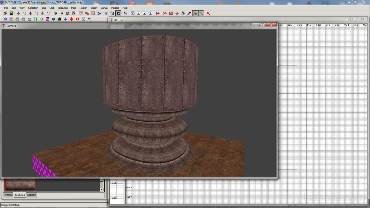
The Final Patch Mesh Pillar

The end result of all that hard work, very nice.
[1: Patch Mesh Basics | 2: Multiple Meshes | 3: Advanced Patches | 4: Pillar Support]

