Render a Skybox Environment Map
Skyboxes are a cheap way to provide background visuals beyond the player reachable objects of a Scene. Essentially just a series of panels projected onto the inside of an environment, Skyboxes can be produced by rendering a special scene containing all the elements that need to appear – sky, ground, background objects and other items.
The following tutorial discusses this process, of setting up and rendering a basic skybox, using "Bender Render" ("Blender Internal"), for use in game development. A basic understanding of Blender is recommended but not absolutely necessary to get the most from the content below.
Download: KatsBits – Skybox Example (c200 KB | *.blend, *.tga)
Resources
– Skybox using Cycles
– Skybox in Blender 2.49
Skybox set-up
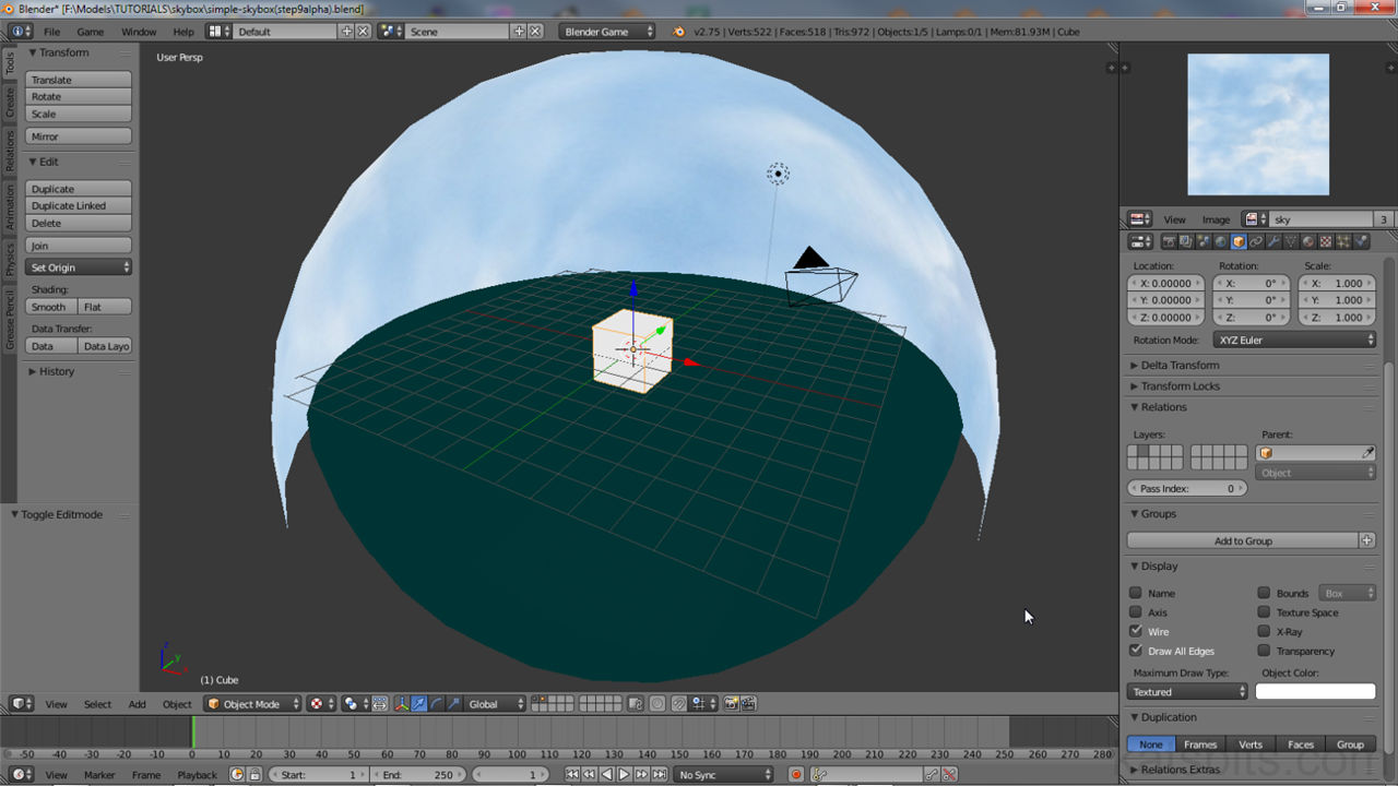
The simplest form of Skybox is a sphere split horizontally into two halves at its mid-point; an upper section representing ‘sky‘, and lower for ‘ground‘ (up to and including the horizon). The ‘sky’ section is usually a little larger than the ‘ground’ so it can overlap the lower section to compensate for missing areas due to alpha masking at the horizon (skyline masked to represent distant trees, cityscapes etc.). At grid-centre to the two domes (half-spheres) is a cube typically assigned an "Environment Map" Material – this essentially represents the six sides of the eventual cubic Skybox, the ‘point of view’ from which the Scenes contents will be rendered.
Design note: essentially a Skybox can be rendered from anything within the 3D View but for convenience, usually because the resulting map is to be used as an environment background, they are generated using a sphere split in to two halves. This forms a boundary. Within this any placed object will be rendered as part of the eventual map. In other words, although in most instances a Skybox is generated to display just ‘sky’ and ‘ground’, the Scene used to create that image can contain any manner of objects – models represented buildings for a cityscape, trees for a distant forest and so on. So long as these ancillary items sit inside the dome (and within range of the renderer) they will be baked to the Skybox image.

The basic elements used to render a Skybox environment map, an upper and lower dome representing ‘sky’ and ‘ground’, and a reference point, usually located grid-centre, which forms the point of view from which rendering takes place ("Camera" and "Lamp" objects visible in the Scene are not explicitly used for Skybox rendering)
Make a Skydome
To create a simple Skybox generator the first elements to set up are the upper and lower domes for the ‘sky’ and ‘ground’. Starting with a "New" Scene in Blender ("File » New"), select the default Cube and move it to an unused layer; right-click the object then press "M" to access the "Move to Layer" pop-up, left-click one of the buttons selecting the layer to which the object will be immediately moved (it will disappear from view).
Design note: this doesn’t remove the Cube from use, it just puts it to one side ready for use later in the process. If Blender is set up to load an empty Scene a Cube will need to be added – press "Shift+A" to access the "Add" menu and select "Mesh » Cube" from the options available. Or from the Tool Shelf to the left, click the "Create" tab then the "Cube" button to place a cube object in the Scene at the Cursor (subject to Blender version). Note also that if the Scene is completely empty a "Camera" entity must be included else the render process will error out with the "No camera found in scene" message when it attempts to render the Skybox. If a "Camera" is present do not delete it.

The Skybox is made using Blenders default Scene, which typically contains a ‘Cube‘, a ‘Camera‘ and a ‘Lamp‘ object. Although the lamp and camera are not explicitly used for Skybox generation, the latter item needs to be physically in the Scene (even though it’s not the point of view through which rendering takes place)

The default Cube is in the way at present but rather than delete it, it can be moved to another layer for use later on in the process. Press "M" and left-click a button to move the object
With the Cube moved out of the way for now, the next step is to place a "UV Sphere" mesh object in the Scene to be used for the ‘sky’ and ‘ground’ elements. To do this, from the 3D View Header left-click the "Add" menu option, or press "Shift+A", and select "Mesh » UV Sphere" from the available options. A small spherical object will appear centred on the Cursor and accompanied by an "Add UV Sphere" properties panel at the bottom of the "Tool Shelf" (press "T" if not visible) – the default values can be left untouched.
Design note: depending on the version of Blender used, an alternative to using "Shift+A" is to click the "Create" tab in the "Tool Shelf" and then on the "UV Sphere" button to place the appropriate object in the Scene. The sphere will appear wherever the "3D Cursor" is located, which should ideally be at grid-centre. If not the mesh can be moved there by changing its ‘XYZ’ "Location" data under "Object" properties – click the "Object" Properties button (displays an orange cube) and scroll down to the "Transform" sub-section. Change the "X:", "Y:" and "Z:" values for "Location:" so each reads "0.00000"; because the spheres Origin is located centre-of-mass (the small point that appears, usually at the centre, when an object is selected), changing "Location" values will reposition the sphere to be dead-centre of the 3D Views grid.

As the Skybox is actually made from a sphere one needs to be added to the Scene. Press "Shift+A" and select "Mesh » UV Sphere" or use the "Add" menu in the 3D View Header, choosing the same options. An object appears along with a set of properties (use default settings)
The sphere is relative small by default, and as the Cube previously moved temporarily to another layer will be used later on, needs to be resized so its larger – the Cube should fit inside the completed dome. With with sphere selected (right-click), press "S", hold down "Ctrl", and then drag the mouse away from the item to incrementally "Scale" the object larger. Left-click to confirm once a suitable size is reached.
Design note: the sphere should be at least large enough for the default cube to sit comfortably inside without touching the outer, in the example shown below, "20" ‘Blender Units’. When using the 3D Widget to manipulate objects, to the far-left of the 3D View Header a series of numbers and statistics appear that provide size related feedback – using "Ctrl" engages ‘grid-snap’ so the numbers shown will jump in fixed increments. Alternately to using the manipulator widget and shortcuts, an objects size can also be changed in "Object" Properties by altering the "X:", "Y:" and "Z:" values under "Scale:". Or the "X:", "Y:" and "Z:" attributes associated with "View" properties, "N", under the "Dimensions" sub-section.

The default "UV Sphere" object is relatively small so needs to be resized to fit the Cube inside at a later stage in the process. SImply right-click to select and press "S" to "Scale"
Next the sphere needs to be split into two sections for the ‘upper’ and ‘lower’ elements of the Skybox. Whilst still selected press "Tab" to toggle into "Edit Mode" (or select "Edit Mode" from the "Interaction Mode" selector in the 3D View Header) then press "B" to activate and use "Box Select" to left-click drag out a drawn selection area over the upper half of the mesh, which then highlights to confirm.
Design note: making a selection that needs to include the front and back of an object may require switching to "Wireframe" mode to make the selection easier. Press "Z" to enable "Wireframe" or click the "Display Mode" button in the 3D View Header. Alternatively from the Header again, click the "Limit selection to visible" button to enable/disable as appropriate to make selections. Note also that before making a selection the mesh may need to be cleared of any previous selections by pressing "A", "(De)select All".
Once selected the upper section can then be detached as a completely independent object using the "Separate" function. To do this, from the "Mesh" menu option in the 3D View Header click "Vertices » Separate » Selection" (or alternatively press "P » Selection"). This detaches the vertices creating a brand new object whilst leaving the unselected elements alone.
Design note: when using the "Mesh" Header menu option, "Separate" is only available under "Vertices" whereas when using the shortcut, "P", "Separate" is accessible as a pop-up in "Vertex", "Edge" or "Face" select mode.

Press "B" to use "Box Select" to highlight the upper half of the mesh. This can then be detached, using "Separate", as a completely independent object whilst leaving the lower half untouched

Once the selection is made from the "Mesh" menu click "Separate » Selected" to detach the highlighted vertices as a completely unique object…

… which now means the sphere is made from two domes, one each for the ‘sky’ and ‘ground’
The final adjustment to make is to increase the size of the upper section slightly so its larger than the lower, which it can overlap slightly. To do this press "Tab" to exit "Edit Mode" and making sure the mesh is selected press "S", then "Ctrl", to "Scale" the upper dome a little whilst snapped to the grid. Left-click to confirm. Once done left-click drag the "Z" axis handle of the manipulation widget (blue handle) and move the upper dome down so the first row of faces belonging to both lower and upper overlap. Release LMB to confirm.
Design note: with "Ctrl" pressed when moving the mouse to rescale the object, one ‘snap’ (a unit of fixed distance based on grid cell sizes) should be sufficient an increase in size. When moving the object either left-click drag the blue handle, setting a new position on release. Or press "G" to activate the widget, then "Z" to lock movement to the vertical axis. Left-click to confirm. The overlap is somewhat important because it acts as a ‘tolerance’ for the lower to be alpha masked at the horizon – if there were no overlap the process would render gaps as ‘black’ (or whatever colour is set as the Scene background).

To allow a small degree of tolerance for the grounds horizon to be inclusive of alpha masks and transparencies there should be some overlap between the upper and lower domes. Once rescaled slightly, move the upper mesh down so the first row of faces overlap between the two
Initial Materials
Once the upper and lower dome meshes are set up they next need to be assigned a basic Material before then being UV Unwrapped and assigned their respective images, essential to ensure the eventual Skybox is rendered correctly.
Design note: at this point Materials are assigned using default values with perhaps a change to the "Diffuse" colour for ease of identification – more complex properties can/are set later on in the process.
To add the Materials select the upper dome and from within "Material" Properties click the button titled "+ New" just below the empty aperture at the very top of the panel. A set of properties and options will immediately appear. In the "Diffuse" sub-section left-click the small bar tined off-white, a colour-picker will be shown. Left-click somewhere in the wheel to make a selection then press "Enter" or left-click elsewhere on-screen to confirm. In the "Material datablock ID" text input field directly under the aperture (which now displays the Material data being edited) left-click and type an identifying name, "sky" in this instance. Press "Enter" to confirm or left-click elsewhere on-screen.
Design note: objects tend not to have Materials assigned when added to the Scene by default but if one is available simply change the "Diffuse" colour and "Material datablock ID" for each to uniquely identify them. As the lower and upper were previously part of the same object any changes to pre-existing assigned Materials will duplicate. To change this select either object and to the right side of the datablock input field click the "+" button. This makes a new unique instance of the original Material, duplicating and propagating over it’s options and settings for independent editing.

Once the Material has been created change the "Diffuse" colour to make it easily identifiable and assign a unique "datablock ID" ("sky" in this example)
Next in "Texture" properties, again click the button marked "+ New" to generate a set of default options. Left-click the "Unique datablock ID name" input field directly under the aperture list (which now also displays the Texture data currently being edited) and type a new name, "sky" in this instance. Press "Enter" to confirm or left-click elsewhere on screen. Change "Type:" to "Image or Movie" by selecting that option from the drop-down menu. Then from the "Image" sub-section click "+ New" to access the "New Image" dialogue, editing the "Name", "Width" and "Height" of the image to be generated as appropriate. Click "OK" to create and automatically associate the new image with the Texture and Material data. Repeat the steps so both objects each have their own "Material", "Texture" and "Image" data.
Design note: the result should be two independent Materials, in this instance "sky", tinted light-blue and, and "ground", tinted bright-green. For more information on using Materials with "Generated" images click here.

In "Texture" Properties, which should be blank, left-click an available slot in the aperture (red/white checker icon) then click the "+ New" button to generate a generic set of options

Scroll down to the "Image" sub-section and click the "+ New" button; the "New Image" dialogue appears allowing entry of some basic image information – ‘name’, ‘size’ and ‘type’. Left-click "OK" to create

This initial phase simply generates a basic Material that makes use of default data and options, and assigns a generated image that will be used once the object is UV unwrapped

Repeat the process for the remaining dome object so it too has an independent Material, (‘green’ shown to identify ‘ground’) with generated image assignment
UV Unwrapping
Once the initial Materials are in place the images generated during that process can then be assigned to the upper and lower domes though "UV Unwrapping".
Design note: although there are a number of different ways objects can be textured and UV unwrapped, for game related content the application of standard Materials and "UV" mapping is sufficient for purpose.
As much of the UV mapping process takes place in the "UV/Image Editor" it will need to be visible, but not necessarily the focus of the User Interface. So either, swap the "Outliner" view top-right for the "UV/Image Editor" by left-clicking the "Editor type…" button to the left-side of the Header, selecting the option from the list. Or from the main application Header running along the top of Blender click the "Choose Screen Layout" button, selecting "UV Editing" from the the options available.
Design note: because the UV maps being generated for these types of projects are relatively simply there is no real need to switch completely to the UV/Image Editor, so long as it can be seen and basic manipulations are possible, it can occupy a smaller area than might otherwise be used, subject to User preference.
Once the "UV/Image Editor" is visible, select the upper dome and "Tab" into "Edit Mode". Select the entire structure of the mesh, "A", and then from the 3D View Header select "Mesh » UV Unwrap » Unwrap". Alternatively press "U" then select "Unwrap". This unwraps the objects UV’s as a flat grid of points and lines, which appear in the UV/Image Editor.
Design note: when using "A" to "Select All" the key may need to be pressed twice, once to DE-select active selections then once again to RE-select everything.

Once Materials are assigned each mesh can be UV unwrapped so the ‘Image’ previously generated during Material set-up can be applied to the object – as the UV/Image Editor is needed swap out the "Outliner" or select the "UV Editing" layout option
To assign an image to the newly generated UV Map, from within the "UV/Image Editor" whilst the objects UV’s are visible, click the "Browse Image to be linked" button in the Header and select the named entry associated with the image previously generated per the Material that’s assigned to the mesh, in this instance "sky".
Design note: images generally cannot be assigned to UV’s unless those UV’s are visible in the "UV/Image Editor", even if the image is available and selectable in the "Browse Image to be linked" list (such selections will appear in the UV/Image Editors workspace but not on the mesh). To ensure selections are correctly assigned the entire mesh needs to be actively selected in "Edit Mode".
The UV/Image Editor will display the image selected in the workspace with the UV map superimposed over the top, both of which are confined to a fixed area determined by the dimensions of the image itself (typically a ‘square’ or ‘rectangle’ shape). In the 3D View the image may not appear mapped to the mesh, if this is the case press "Alt+Z" to switch "Display Mode" to "Texture" confirming assignment. Repeat the process so both domes are UV Unwrapped and mapped with their respective generated image.
Design note: images can be assigned to UV’s in part or whole independently of the Material they may be associated with – be aware that doing so may cause rendering issues should the final Material contain more complex properties supposed to affect the image and how it should be displayed.

With the mesh UV Unwrapped the previously generated image can be assigned using the UV/Image Editor by selecting the entry from the "Browse Image to be linked" list ("sky" in this instance)

The process of UV Unwrapping and assigning an appropriate image to an object needs to be repeated for the remain half of the full dome ("ground" in this instance)

For clarity the UV map and image assignments shown in "UV Editing" layout mode – "UV/Image Editor" to the left, the "3D View" to the right side of the screen
extra Material settings & Replacing Images
Once the upper and lower domes have been UV mapped their Materials can be further edited to add a secondary setting that changes the way light affects the scene, one that essentially makes selected items appear ‘full-bright‘. This is the "Shadeless" property and by activating, the scenes lighting no longer has influence over the way objects appear lit, which in-turn ensures the rendered Skybox contains no out-of-place shading or shadows.
Design note: although "Shadeless" materials may appear ‘lit’ or ‘self-illuminating’ they are not the same as those able to properly ‘cast’ or "Emit" light – materials that can be set up to act as a source of light. For Skybox rendering "Shadeless" is useful, depending on requirements, because Materials can then processed and illuminated uniformly regardless of the Scenes contents.
To activate "Shadeless" select the object to be affected then under "Material" Properties scroll down to the "Shading" sub-section and left-click the checkbox to the left of the heading to activate. The image will immediately appear flat-lit in the 3D View, visually confirming the change. Repeat the process for the remaining dome object.

From the "Shading" sub-section of "Material" Properties, activate "Shadeless" by left-clicking the checkbox thus disabling the effect light and shading has on the object – in comparison note the lower dome, the light in the Scene is not large or powerful enough to illuminate it so it will appear black until the "Shadeless" property is set for its Material

Once both Materials have been set to "Shadeless" they will appear flat lit – depending on the Scene and background requirements this is useful to ensure everything appears uniformly to the renderer
Once "Shadeless" is set, check each Materials "Image" properties to ensure the correct data is loaded in for use, for example swapping out the temporary "Generated" data for any actual bitmaps to be rendered.
Design note: using "Generated" data has some initial advantages for Materials in that their general size can be changed on-the-fly without unduly hindering other aspects of development. It can also be saved out for editing, reloaded back in once the final details are determined. To save generated image data, from the UV/Image Editor use the "Browse Image to be linked" button to select the unsaved data so it’s active in the viewport (in instances where more than one datablock is available), then from the "Image*" Header menu select "Save As Image" or "Save A Copy", the difference being the former replaces the image currently active to the Material then references an an actual bitmap, the one just saved, versus the latter which saves a ‘copy’ of the active data whilst leaving the active, but generated, image in place.
To load a replacement, in "Texture" Properties scroll down to the "Image" sub-section and first left-click the "Source" drop-down menu and select "Single Image", this informs on the type of image data being represented, in this instance a single image bitmap, then click the "Open file browser" icon. The interface will switch to the "File Browser". Find and then left-click select the bitmap to be used and click the "Accept" button top-right. Blender will return to the previous screen with the image loaded into the Material and displayed on the object. Repeat the process for the remaining object. Once done the basic set-up of the background is complete and ready for use. Next the Cube object previously moved to another layer needs to be prepared.

Before loading in a replacement image some of the Materials settings need to be changed. In "Texture" Properties switch "Generated" to "Single Image"[1] then click the "File" button[2]… (the mesh may appear ‘pink’ during at this point indicating an image (bitmap) has not yet been assigned or is missing)

In the "File Browser" that opens, left-click select the bitmap that’s to be loaded in replacing the previously "Generated" image data then click the "Accept" button top-right

The "Generated" image data replaced with more appropriate ‘sky’ and ‘ground’ bitmaps for both upper and lower dome. The Scene is almost ready for rendering
EnvBox, Material & Settings
The second aspect of setting up a Skybox for rendering is to add, or create, an "Environment Box" (or "EnvBox") to serve as the ‘camera’, or the point of view, through which the Scenes contents are considered and rendered. In this instance the default Cube previously moved to another layer.
Design note: the standard "Camera" object cannot be used in a general sense for environment map rendering because it only looks at the Scene from a single fixed point-of-view. Using a cube solves this because each face of the EnvBox represents a ‘perspective’ or ‘view’ of the scene, a ‘side’ (‘left’, ‘right’, ‘front’, ‘back’ etc.) of the final rendered "Environment Map". The physical size of the cube isn’t so important as its shape, which should be cubic.
First if the cube was moved to another layer left-click the "Visible Layers" button representing that to display the object, then make sure its located at the Scenes centre. To do that right-click the object and check its "Location" data in "Object" or "View" Properties ("N"), each "X:", "Y:" and "Z:" value should be "0.00000". If not left-click each input field in-turn and type the correct value. Press "Enter" to confirm or click elsewhere on screen.
Design note: the EnvBox should be centred on the Scene because any directional deviations may cause the resulting image to distort slightly, i.e. exhibit a directional bias towards the direction of offset – if the box is to the right slightly it may result in the left side appearing smaller, an important consideration when rendering a Scene with other objects and items in it. Additionally note that "scene centre" may not be the same as "grid-centre" – the object should be centred relative to the contents the the Scene being rendered, which may not tally with the grid.

The default Scene Cube to be used as the "EnvBox" through which rendering will take place – ensure the object is centred on the Scene being rendered (which may not position it ‘grid-centre’)
Once positioned add a new Material to the cube. To do this click the "Material" Properties button then "+ New" to generate an entry – the Material panel will populate and the cubes appearance may change slightly in the 3D View. From here scroll down to the "Shading" sub-section and active "Shadeless" by left-clicking the checkbox. The cubes appearance may again change in the 3D View by way of visual conformation.
Design note: activating "Shadeless" for the ‘EnvBox’ serves the same/similar purpose as for the domes, it ensures the final render is not unduly affected by lighting and shading (subject to requirements of the scene).

Once a Material has been assigned to the cube, from "Material" Properties activate "Shadeless" (under "Shading") to disable the effect light/shading has over objects in the Scene and the Environment Map during the rendering process
Next in "Texture" Properties change the "Type" to "Environment Map" by selecting that option from the drop-down menu below the ‘name’ input field. A set of properties will appear under a new "Environment Map" titled sub-section. Here left-click "Static" to activate single image rendering[1]; make sure "Mapping:" is set to "Cube"[2]; change the "Resolution:" of the map to be rendered[3]; and optionally alter the "Clipping:" distances[4] to make sure the entire Scene is included for consideration and rendering.
Design note: when changing the maps "Resolution:" bear in mind the value used relates to the shortest side of the map, usually the vertical axis; at "1024" the result would be an image that’s 1536 pixels wide by 1024 pixel height, i.e. six 512×512 panels (one for each side of the EnvBox cube) forming a 3W x 2H grid.

For the cube to be useful the "Type" of Material its mapped with needs to be changed to "Environment Map" by selecting the option from the drop-down list in "Texture" Properties…

… which makes a set of additional "Environment Map" related properties appear – set "Static"[1], make sure "Cube"[2] is selected, change the "Resolution:"[3] and check "Clipping: (Start/End)"[4] to ensure the contents of the entire Scene are being included in the render
The final and most important setting to change is "Viewpoint Object"[5], the item Blender uses as the point-of-view from which rendering/projection of the environment map takes place. In this instance the cube. To select it click the orange icon on the left-side of the "Viewpoint Object" input field and select "Cube" from the list of entries available. Once done the Skybox is ready to be rendered.

The most important aspect of rendering Environment Maps is to set the object which forms the renderer’s point of view of the Scene. This is done changing the "Viewpoint Object" property[5] to use a specific item, in this instance the Cube (called "Cube"), selected from the ‘object list’
Render Environment Map
Before rendering the environment map an image format needs to be set in "Render" Properties because the option is not provided at save. Click the "Render" Properties button (‘camera’ icon) and scroll down to the "Output" sub-section, here click the "File Format" drop-down menu (bottom-left of the section) and select "Targa Raw", "BMP", "Tif" or other loss-less image format.
Design note: preference should be given to the use of ‘raw‘ or uncompressed image formats, or failing that to ones that makes use of lossless compression. Avoid jpg or other aggressively compressed formats at all costs as they often contain compression artefacts, banding, patterns etc., that can be magnified in-game, especially when projected as an environment background.

The image format the map is rendered to is set in "Render" properties under the "Output" sub-section – click the "File Format" drop-down menu (bottom-left of the section) and select a lossless format such as *.tga, *.bmp or *.tif
Once the format is set make sure all elements that need to be rendered are visible in the 3D View ("Shift+LMB" layers where used). Then to start scroll back up to the top of "Render" Properties and click the "Render" button (displays a ‘camera’ icon). Blender will switch to the "Render View" and sequentially process the Scene (time taken will vary), rendering each projection (six) of the EnvBox as an image before finishing with a render from the camera objects point of view.
Design note: double-check an actual "Camera" object is present somewhere in the Scene else the process will fail with a "No camera found in scene" message. The image rendered as a result of the camera is not part of the environment map and can be ignored/discarded.

Ensure ALL items to be rendered are VISIBLE in the 3D View before clicking the "Render" button (the EnvBox doesn’t specifically need to be selected to render the Scene)

When processing the Scene the Environment Map attributed to the Skybox is rendered first (six panels, one for each face of the EnvBox Cube)…
")
… until the final image to be rendered is the Camera view (which is to be discarded) – note that a "Camera" object needs to be in the Scene else render will fail (camera doesn’t need to point at anything or be assigned any properties)
Once the process completes the rendered environment map will be available for saving. To do this make sure the ‘EnvBox’ object is selected so the rendered data is active, then from "Texture" Properties scroll down to the "Environment Map" sub-section and click the black downward pointing arrow top-right of the section[1]. A drop-down menu will appear with a number of options, select "Save Environment Map". This opens the "File Browser" allowing a location to be set and a file name to be written before the "Save Environment Map" button top-right is the clicked to confirm and save with Blender returning to the previous screen once done.
Design note: when saving the rendered map, the file extension may need to be manually included because *.blend is present by default (which may cause some confusion when looking for and trying to open the image).

Save the rendered map back in "Texture" Properties where the option to "Save Environment Map" becomes available (option is greyed out when no map is available for saving) – note the ‘EnvBox’ object needs to be selected to highlight the data before it can be saved to file…

… in the "File Browser" type the file extension being saved to, i.e. *.tga, *.bmp etc., and then click the "Save Environment Map" button top-right

The saved *.tga map open in image-editor (bright-green indicates areas where an alpha mask is present but not correctly compensated for by the rendering process – see below)
Alpha Masks & Transparency
Given the nature of Skyboxes they typically include some degree of transparency or alpha masking, usually at the horizon, to avoid the transition point between key elements being a straight, hard line. Although there are a number of ways to approach the inclusion of alpha transparency, overall the features use requires each Material have "Use Alpha" enabled in "Image" Properties[1], without this setting, even if Materials do have transparency set-up, Blender will ignore the effect.
Design note: Materials are initially created with "Use Alpha" active by default. If alpha-masking or transparency is not found Materials are treated as standard.
Simply activating "Use Alpha" doesn’t necessarily mean transparencies are used however. For that, various properties need to be set depending on the type of transparency needed and the general behaviour required of the Material involved.

By default Materials have the "Use Alpha" setting active in "Texture" Properties even in instances where transparency is not used (the effect is ignored otherwise)
To set up transparency for Skybox rendering, first the Material itself has to be rendered transparent, then "Texture" properties have to be set so they use the alpha channel of any images loaded into the Material.
Design note: if a Material is not transparent its "Diffuse" colour will be visible when the Scene is rendered (the bright-green seen in the final render above). Essentially because Materials comprise three distinct layers – "Material", "Texture" and "Image" – each needs to be set up to behave correctly with respect to transparency; a corollary would be to think of three sheets of craft-paper stacked atop each other, for ‘transparency’ to work each layer has to be cut in a way that corresponds to the upper most layer and any cut-out shapes it contains. If not, the cut-out and last whole layer are all that’s seen, any subsequent layers then being obscured from view as a result.
To do this, from "Material" Properties scroll down to the sub-section titled "Transparency" and left-click the checkbox to activate. Here ensure the "Z Transparency" button is active (appears blue) and that the "Alpha:" input field is set to "0.000" ("Alpha: 0.000"). This forces the Materials "Diffuse" colour (and other properties that might be set) to render invisible so it has no affect or influence the outcome of processing the Scene.
Design note: the properties and options associated with "Transparency" are usually not on display and require the small downward pointing arrow to the left-side of the heading to be clicked to expand and expose them for use.

For transparency to work the Materials "Transparency" properties needs to be set so the "Diffuse" colour (and/or other options) are rendered invisible – check (or select) "Z-Transparency" is active and then change "Alpha: 1.000" to "Alpha: 0.000"
Next in "Texture" Properties scroll down to the "Influence" sub-section and from the "Diffuse:" group of options, activate "Alpha:" by left-clicking the checkbox (leave the value, "1.000", untouched). Upon activation the 3D View will update to display the areas subject to alpha transparency, confirmation the Material is now set up correctly and ready for rendering.
Design note: for standard rendering the value attributed to "Alpha:" can be left as is. However it can be changed to reduce the level of transparency determined by the image if needed with a range between "1.000" (positive) and "-1.000" (negative) – the former uses the alpha as presented, the latter inverts it.

With the "Diffuse" properties set so they display invisible, in "Texture" Properties activate "Alpha" so the image based alpha-channel can influence the rendered transparency for the entire Material

Mid-way through rendering the ‘ground’ section is shown with a fully masked horizon as determined by the ‘transparency’ and ‘alpha’ settings of the Material (without these settings the image displays partial inclusion of the "Diffuse" colour, bright-green in this instance, where the image alpha-mask affects "Texture" but not "Material" properties)

Final environment map rendered with skyline correctly defined by the image based alpha-mask and transparency properties of the ground mesh and the Material assigned to it
Organisation & Orientation
The final rendered Environment Map is essentially a flattened cube with the organisation and orientation of each tile determined by Blenders Global axes. This means;
- "Front" is on the positive "Y" axis ("+Y", centre-top).
- "Right" is to the positive "X" axis ("+X", right-top).
- "Up/Top" is on the positive "Z" axis ("+Z", centre-bottom).
The upshot of this when using the rendered images outside Blender typically means the map will need to be edited and the tiles rearranged to fit requirements and/or cut into, and saved as, separate images where the use of a single map is not appropriate.
Design note: tiles currently cannot be reorganise from within Blender so some manual editing may be required, subject to the way ‘environment maps’ are set up in the destination technology. The prospect of having to do this highlights one of the reasons lossless image formats should be used when saving maps as compression and anti-aliasing can cause ‘bleed’, ‘smudging’ and other visual artefacts that are tricky to correct effectively, especially between strong or bright colours, an issue that becomes more apparent where tiles need to be cut up and rearranged.

The organisation and orientation of each tile within the map may differ between source (Blender) and destination technology (where the map is to be used) so some editing map be necessary, keeping in mind their respective position relative to the whole
Process Summary
The following is a summary of process to set up a simple Skybox in Blender to render an "Environment Map". From the default Scene;
- Sky and Ground Domes
- add a UV Sphere, resize so the default Scene cubes easily fits within it.
- split the sphere into two separate objects, an upper and lower dome.
- resize the upper slight and overlap the lower.
- assign separate Materials to each upper and lower dome.
- add an Image to the Materials (either generated or bitmap).
- UV unwrap the meshes using simple UV maps.
- assign the respective image the each UV map and object.
- set Materials as "Shadeless".
- EnvBox
- assign a new Material to default Scene Cube.
- set Material as "Shadeless".
- switch Material "Type" to "Environment Map".
- set "Environment Map" properties as "Static", "Cube" and change "Resolution".
- set "Viewpoint Object" to "Cube" (name of default cube).
- Render Scene
- in "Render" Properties set image format to "tga" or other lossless format.
- click "Render" to process the Scene.
- save the results in "Texture" Properties.
Conclusion
The most basic form of Scene to set up and render is a sphere of two parts as described above. It works for purpose largely because of its simplicity, especially with respect to the way images are used and UV Mapped to each object. For more flexibility however, Scene can be more complex in terms of their general construction, separate objects being used for different elements. Scenes can also contain other items depending on what the background is eventually to represent, although care should be taken to avoid issues of ‘magnification’ due to in-game projection mechanisms.
Video
The following video shows the basic process described in the above tutorial.

