Render A Skybox Using Cycles
Rendering a Skybox in Cycles Render isn’t possible the same way it is for Blender Render (Blender Internal) because the engine is missing a number of the same core elements that would otherwise allow for the production of a workable Skybox; crucially the “Environment Map” Material; and the ability to set Materials as “Shadeless“. Having said this however, it can be done as a ‘workaround’, using the properties and options Cycles Render does have available.
The following tutorial discusses this process, of setting up and rendering a Skybox to produce an Environment Map using Cycles Render and properties specific to that engine. A basic understanding of Blender is preferred but not strictly necessary to get the most from the below information.
Download: Cycles Skybox Example (c. 600 KB | *.blend, *.tga).
Skybox basics
Skyboxes are relatively straightforward to make and render using Blender Internal because is has the necessary features to generate an image map that’s correctly lit relative to an environment. As mentioned briefly in the Introduction, the two main aspects that cater to this are “Shadeless” Materials and the ability to render a specific type of image based on a ‘cubic’ perspective, an “Environment Map“. Cycles Render (currently) has neither.
Design note: by “cubic” it is meant that rather than an image being rendered from a single given point-of-view, the renderer is able to account for multiple perspectives – six for an “Environment Map“, each ‘angle’ representing a specific view of the Scene, “up“, “down“, “left“, “right“, “top” and “bottom“.
This being the case doesn’t mean Skyboxes cannot be rendered using Cycles, rather that to do so the problem has to be solved indirectly, using the options Cycles does have available. For Skyboxes that means using an ‘emit‘ Material and ‘baking‘, rather than ‘rendering’, a type of surface property associated with a specific object present in the Scene.

The most basic type of Skybox useful for rendering with Cycles Render is simply made from two overlapping domes with an object (typically a cube) in the centre – although a ‘Lamp’ and ‘Camera’ object are present they generally go unused when using Cycles Render
Making a Skybox
The most basic Skybox has two main components; 1) an ‘environment’ and 2) an ‘origin‘ Object. The former at its simplest is a sphere split in half to represent ‘sky’ and ‘ground’ surfaces. The latter is a ‘cube’ primitive that functions as the point of view from which the Scene is observed. As briefly mentioned in the Introduction however, the same types of Entities available under Blender Render are not present using Cycles Render so the mechanism to achieving points “1” and “2” differ.
Design note: Cycles Render is a much more powerful rendering system than Blender Render but it does have some caveats in the way some features or expressions are not available when it might be otherwise thought they should (because they would appear to be ‘core’ components of a particular outcome).

The Skybox Scene starts from Blenders default ‘start-up’ file so contains a cube ‘Primitive’, a ‘Lamp’ and a ‘Camera’ object – the latter two are not used when rendering Skyboxes using Cycles
To make a basic environment start with Blenders default Scene and “Add” a “UV Sphere” (“Shift+A » Mesh » UV Sphere” or from the 3D View Header left-click “Add » Mesh » UV Sphere“), which immediately appears in the 3D View at the 3D Cursor.
Design note: when adding objects to a Scene they appear by default at the 3D Cursors location so ensure this is positioned at ‘grid-centre’, or at least at the centre of the Scene being built – open “View” Properties, “N” (or from the 3D View menu select “View » Properties“), scroll down to the “3D Cursor” sub-section and check each “X:“, “Y:” and “Z:” coordinate value is set to “0.000“.

The most basic Scene to render is a Sphere. From the “Add” menu select “Mesh » UV Sphere” to place an object at the cursors location (centred on the Scene) – a set of properties will also appear bottom-left of the Tool Shelf that can be used to make adjustments although most defaults are initially fine
Next re-scale the new object. Press “S” then hold down “Ctrl” to grid-snap and move the mouse to increase the spheres size so its at least three or four times larger than the default cube. Left-click to confirm.
Design note: for more precision when re-sizing objects, immediately after adding the item; increase its “Size” (the “X:“, “Y:” and “Z:” values) in “Add UV Sphere” Properties which appears bottom of the Tool Shelf (“T“); from “Object” Properties by increasing the “Scale:” value in “Transform:“; or by increasing the objects “Dimension:” in “View” Properties (“N“). Either way the result is the same, changing the appearance of the selected item, albeit through slightly different data-types, “Size“, “Scale” or “Dimension“.

Type a new value to resize the sphere by increasing its “Size” in “Add UV Sphere” properties (if still visible), or press “S” then hold “Ctrl” to scale snapped to the grid (release to confirm)
With the sphere in place, select it and toggle into Edit Mode, “Tab“. Press “A” to deselect any active selections (or “Select » (De)select All“), then “B” to activate “Border Select” (or “Select » Border Select“). Draw an area covering the upper half of the mesh and then press “P” to “Separate” the section as an independent object (or “Mesh » Vertices » Separate » Selection“). This creates two domes; an upper ‘sky’ and lower ‘ground’. Press “Tab” exiting Edit Mode and select the newly made upper dome. Press “S” then “Ctrl” and re-scale this object whilst grid-snapped, making it slightly larger than the lower section. Left-click to confirm. Finally, left-click the blue handle of the manipulator widget and move each object so they overlap in the middle.
Design note: to aid selection from the “View” menu in the Header click “Front” (“View » Front“) then again selecting “View Persp/Ortho” (“View » View Persp/Ortho“) to flatten the Scene, making selection easier (shortcuts; “numPad 1“, “numPad 5“). When scaling an individual item in Object Mode, the action defaults to using its Origin as the point around which change is made as opposed to the centre of mass of a selection, in this instance that ensures the modification is evenly applied and scaled relative to the original sphere. When overlapping, the amount only needs to be enough to cover the bottom-row of the upper mesh and the upper row of the bottom mesh.

The simplest background to use as a Skybox requires an ‘upper’ and ‘lower’ sections representing the ‘sky’ and ‘ground’ so “Border Select” (“B“) the entire upper half of the sphere in Edit Mode…

… then detach the selection using “Mesh » Vertices » Separate » Selection” (shortcut “P“), creating a completely independent object

Two separate objects, an ‘upper’ and ‘lower’ that can now be independently edited and assigned their own individual materials

The domes can be left as is although preference should be given to overlapping to compensate for the effects of alpha transparency, along the horizon especially. To ensure this principle (overlap) works effectively select the upper dome and resize so its slightly larger than the lower – press “S“, hold “Ctrl” to grid snap, left-click confirm
Once the two halves of the Skybox have been positioned and scaled, select each in turn and “Tab” into Edit Mode to assign a UV Map. To do this press “A” to select the entire mesh (or “Select » (De)select All“), then press “U” and select “Unwrap” from the “UV Mapping” pop-up menu that appears (alternatively “Mesh » UV Unwrap » Unwrap“). A “UV Map” will be generated from the selection. Press “Tab” to exit Edit Mode and repeat for the remaining half of the Skybox; right-click select the item, “Tab” into Edit Mode and press “A” to select everything (if not already selected), press “U” and again select “Unwrap” from the options to generate a similar simple UV Map for the object completing the process for the domes.
Design note: unless the UV/Image Editor is visible there will be no obvious indication a UV map has been generated, with that said it’s not strictly speaking necessary for the editor to be visible when initially unwrapping an object, so for a quick way to verify without loading the UV/Image Editor, click “Object Data” Properties and check for a “UV Maps” entry; if an object is mapped a listing will appear here.
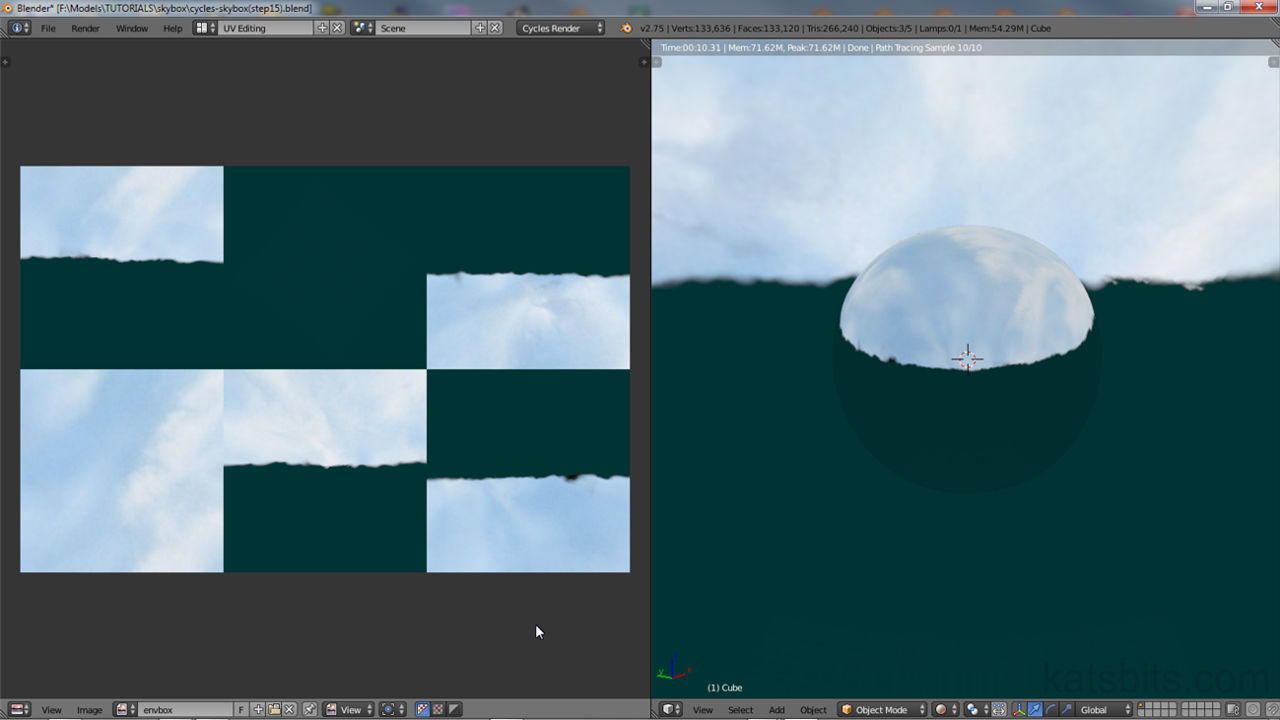
 Shown for clarity in split-screen “UV Editing” layout, the domes simple UV Map is displayed in the UV/Image Editor workspace (within the confines of the “Texture Space” grid) – in Edit Mode, select the entire mesh in the 3D View, “A” and press “U” to “Unwrap” (or “Mesh » UV Unwrap » Unwrap“)

Both upper and lower objects need a basic UV Map assigned, and given the nature of the objects being mapped, a simple ‘flat’ or ‘top-down’ projection is all that’s required
With each dome mapped attention can be turned to the default cube. To render a Skybox properly using Cycles unwrapping the cube differs from the domes in that each face of the cube needs to form a separate UV island within the overall map; they should, or can be, independently selectable ’tiles’, each of which represents a particular Scene point-of-view. To ensure this happens the UV’s can be split using the “Mark Seam” property.
Design note: a distinct advantage to using Cycles for environment map rendering means the UV maps layout can be changed because of the way the technique relies exclusively on the position/location of each UV face, thus the final map can be (re)organised as an “[x] x [y]” grid, a cruciform, or some other ‘shape’ that’s compatible with requirements (not all games use a formalised ‘grid’ layout).
Right-click the cube and “Tab” into Edit Mode. Press “A” to select everything and from the “Mesh” menu select “Edges » Mark Seam” (“Mesh » Edges » Mark Seam” or “Ctrl+E » Mark Seam“), each edge around the cube will highlight an orange colour indicating and confirming assignment. Finally press “U” and select “Unwrap” to generate a UV map (or “Mesh » UV Unwrap… » Unwrap“).
Design note: the default layout will typically be a lop-sided stack of UV’s so the collection fits within the confines of the “Texture Space” grid. Again no outward indication is given that a map has been assigned.
The result to this point is an ‘upper’ and ‘lower’ dome, both of which have been unwrapped and assigned a basic UV Map, and a cube situated at Scene centre, similarly UV unwrapped. No textures or Materials have yet been assigned, which will be done next.

Because the Skybox is actually going to be ‘baked’, the object that forms the skybox itself needs to be unwrapped so each side is a separate element, or “Island”, within the overall UV map. In Edit mode use “Mark Seam” on ALL edges to create a series of ’tiles’ (“Ctrl+E » Mark Seam“)

Once seams have been marked to isolate each face, Unwrap the cube, “A” to select everything, then “U” to “Unwrap“, which will typically unwrap as a three-tiered stack of UV’s in the UV/Image Editor (shown in the split-screen “UV Editing” layout for clarity)
Texturing the Skybox
With upper and lower domes unwrapped images can then be assigned. This is initially done using the “UV/Image Editor” so that; 1) images are applied directly to the UV Map, and 2) by doing so image data is then easily accessible for node-based Materials set up later on (next). To view the UV/Image Editor, from the upper menu running along the top of the application click the “Choose Screen Layout” button and select “UV Editing” from the list. The interface will change to a split-screen layout displaying the UV/Image Editor to the left, 3D View to the right, this allows objects to be selected and their respect UV Maps exposed side-by-side.
Design note: each of the “Choose Screen Layout” options simply (re)organises the user interface to better suit the task associated with the layout selection, it doesn’t specifically change functionally or tool availability beyond the defaults for each Editor. An alternative is to swap one of the active views for the UV/Image Editor via the “Current editor type…” button in the given views Header, or using “Shift+F10” and/or “Shift+F5” shortcuts to toggle between “UV/Image Editor” and/or “3D View“.

Depending on personal preference the “UV/Image Editor” can be displayed as part of the “UV Editing” split-screen layout available under the main Headers “Choose Screen layout” option. Or by simply swapping one of the active windows using the “Current Editor type” button in a given views Header
To assign an image to a UV map select one of the domes in the 3D View and toggle in to Edit Mode (if not already active). To ensure the image is assigned correctly, press “A” to first de-select any active selections, then once again to re-select everything. Upon doing this the UV Map will appear on the left in the UV/Image Editor. From here, click the “Image” menu option in the Header and select “Open Image“. The “File Browser” will appear. Find, left-click select, and load the image clicking the “Open Image” button top-right. Blender will return back to the previous split-screen with the Image displayed in the UV/Image Editor with the UV Map superimposed over the top by way of indicating it is now assigned. In the 3D View exit Edit Mode, select the other dome object and repeat the process, loading in the remaining image, assigning it to the highlighted UV map in the UV/Image Editor.

To simplify the process of setting up node-based Materials later, different images can be assigned to objects using the “UV/Image Editor” – from the Header menu click “Image » Open Image“…

… which opens the “File Browser” where the bitmap asset can be selected (shown with alpha)…

… before being loaded in the open UV editor and assigned to the selected objects UV’s. Repeat for both upper and lower dome objects applying separate images to each respective unwrapped UV Map
For the cube ‘envbox’ object assigning an image differs slightly because its texture will be rendered, all that’s initially required is a placeholder, a temporary “Generated” datablock. To do this, in the UV/Image Editor click the “Image” menu option and select “New Image” to open the “New Image” properties pop-up. Here give the entry an easily identifiable name, e.g. “envbox”, select “UV Grid” as the “Generated type:“, then change the “Width:” and “Height:” values to reflect the size of the eventual map and its orientation, for example “Width: 1,536” and “Height: 1,024“. Once set click “OK” to confirm and generate the image, which appears in the editors workspace.
Design note: the size and general dimensions of the image assigned to the ‘envbox’ cube is determined by the size of a single ’tile’ or UV’d mesh face; if each is 512W x 512H pixels, using a standard 3W x 2H tile grid means the final image is 1536W x 1024H pixels. This can change however based on map requirements, mapped as 6W x 1H grid the generated image would need to be 3,072W x 512H pixels. In this regard single-sheet Skyboxes may present issues due to their size or relative non-traditional power-of-two dimensions.
With the image available, in the 3D View right-click the object and “Tab” into Edit Mode, select everything, “A“. This displays the cubes previously unwrapped UV’s in the UV/Image Editor. Here click the “Browse Image to be linked” button in the Header and select the image just created (“envbox”) to assign it to the cubes UV’s.
Design note: whilst in the UV/Image Editor to assign the image to the cubes UV’s, the ’tiles’ may need to be reorganise where necessary to conform to layout requirements – when unwrapping structures, UV’s don’t always conform to any particular logic; even though the image is set to correspond to a 3W x 2H grid, there may may actually be three rows of tiles and not two (3 tiles, 2 tiles and 1 tile atop each other, instead of 3 tiles by 3 tiles). To reorganise right-click individual UV vertices or faces depending on the selection type (“Ctrl+Tab” to access “UV Select Mode“), and press “G” to free translate (move) each section to fit the layout needed – activate “Snap to Pixels” (“UVs » Snap to Pixels“) to aid placement accuracy when doing this.

To texture the cube an image needs to be created using the “New Image” dialogue – select the mesh in Edit Mode to expose the previously unwrapped UV’s then from the “UV/Image Editor” Header click “Image » New Image” to access the dialogue. Change the settings as needed before clicking “OK” to complete, generate and assign to the mesh UV’s

Due to the nature of the workspace area being square the cubes UV’s may need to be reshuffled and edited to fit the generate image (which should be sized to properly fit a set of ’tiles’ – if each tile is 512×512 the image should be 1536×1024 pixels in width/height to accommodate two rows of three tiles)
Once done, with the mouse over the 3D View “Tab” out of Edit Mode then switch back to the “Default” layout by selecting that option from “Choose Screen Layout“. At this point the Scene contains an upper and lower dome and cube object, each UV mapped and assigned separate images. From this point on everything will be done in “Cycles Render“.
Design note: before switching Engine, to view the changes that have been made so far enable “Texture” display (“Alt+Z“) in the 3D View – relative to Blender Render the dome meshes will appear dark/poorly lit because the mesh is inside out – this can be corrected in Edit Mode by selecting everything and clicking the “Flip Direction” button in “Shading/UVs” tab of the Tool Shelf (the mesh being inside-out has no bearing on the final rendering process however). Also, although “Material” and “Render” display can be selected, objects will generally appear default grey without the presence of any underlying Material properties.

The upper and lower domes use separate ‘sky’ and ‘ground’ bitmaps, with the cube assigned generated image data that will be replaced later once the environment is rendered (for purposes of clarity the Skybox is shown above absent the influence of the default Lamp object, and the dome meshes have been temporarily ‘flipped’ outside-in)
Skybox Materials
For the final Skybox to be rendered properly background objects, the ‘sky’ in particular, need to use “Shadeless” materials to ensure they remain unaffected by Scene lighting and mesh shading. Cycles Render however, does not (currently) have a corresponding Blender Internal “Shadeless” property so the effect has to be approximated using “Emission“, a setting that makes surfaces appear uniformly lit because they ‘self-illuminate’ – each face assigned the property is turned into a light source which cancels out shading artefacts (unless a very low ’emit’ level is set).
Design note: the necessity to avoid lighting and shading issues is general in nature and subject to scene/skybox/environment map requirements. In other words, the use of ‘shadeless’ materials is dependant upon the scene being rendered; a night-time cityscape with street lights and other secondary illumination may not need the property (or it’s Cycles equivalent) for example.

Materials and the surfaces should be flat-lit to avoid mesh shading artefacts showing up in the rendered environment map. As Cycles doesn’t have the same “Shadeless” property that’s available when using Blender Internal it has to be approximated using a ‘self-illumination’ property
To set up a faux shadeless Material in Cycles Render, first switch to that render engine by selecting the option from the “Engine to use for rendering” menu in the main application Header (the 3D View will update to reflect the change), then swap one of the available views for the “Node Editor” and adjust its size so a reasonable amount of space is given over to its workspace, for example click the “Editor Type” button far-left of the “Timeline“, a view otherwise unused, select “Node Editor” from the list, and then re-size the view(s) once loaded by adjusting the border between the 3D View and the now visible Node Editor.
Design note: Blender does not include a default ‘node’ layout in “Choose screen layout” but one is relatively easy to create; simply click the “+” button to the right of the “Choose…” input field to duplicate the current layout and then edit the ‘ID’ given by typing a new, more recognisable or appropriate name in the input field other than “[name].001″. Reselect “Default” and rearrange the editors back to their default positions, else the same layout will be kept as Blender doesn’t ‘reset’ the Interface unless a new project is started (which loads the defaults from cache).

Cycles Materials are best edited and managed using the “Node Editor“, using the “Current Editor type” button swap the “Timeline” for example. The “Node Editor” basically comprises a workspace into which nodes are placed, moved, connected to each other, and a Header with context sensitive menu options (only available to the editor)

To ensure node-based Material properties display and render correct switch the “Engine” from the default “Blender Render” to “Cycles Render” selecting the option from the main “Engine to use for rendering” Header menu option
Once the Node Editor is visible, in the 3D View select the upper ‘sky’ object and access “Material” Properties. A panel appears with an aperture and a set of buttons, one of which is titled “+ New“. Click this to generate an initial set of properties in the Materials panel and nodes – “Diffuse BSDF” and (linked to) “Material Output” – in the Node Editor.
Design notes: Cycles materials can be edited in the Node Editor and/or Material Properties, the difference is largely visual and the ease at which complex node groupings can be created versus the same using lists and property options.

Although the objects have images assigned to UV maps, when viewing “Material” Properties they are clear of any settings or options (the panel is essentially blank baring the material list aperture and sparse array of associated buttons)
")
To generate an initial set of Material nodes select the object and click the “+ New” button in Material Properties. This places two nodes, “Diffuse BSDF” and “Material Output“, into the Node Editors workspace
With a set of default nodes in place click the “Add” menu option in the Node Editor and select “Texture » Image Texture” (“Add » Texture » Image Texture“). A node will appear at, and moving with, the cursor. Left-click to place in the workspace. This represents the equivalent “Texture” properties data of Blender Internal, and where the previously UV assigned images are linked. For that, click the “Browse Image to be linked” button (photo icon) in the node and select ‘sky’, the image previously loaded into Blender via the UV/Image Editor. Upon doing this, and by way of confirmation, the 3D View will update to display the image assigned to the mesh.
Design note: assignments will display in the 3D View when “Texture” (“Alt+Z“) or above (“Material” and/or “Rendered” – “Shift+Z“) is the active “Display Mode“.

To create a basic ‘shadeless’ node-based Material first add an “Image Texture” node (“Add » Texture » Image Texture“) …

… and then link the bitmap loaded previously via the UV/Image Editor to the node by selecting the entry from the “Browse Image to be linked” list (in this instance shown as “sky_top_updated.tga“)
Click “Add” again and select “Shader » Emission” (“Add » Shader » Emission“) from the list of available options. Another node will appear in the Editor. Left-click to confirm, then click “Add” once more this time selecting “Input » Texture Coordinates” (“Add » Input » Texture Coordinates“). Again left-click to confirm placement. At this point there will be five nodes, “Material Output” and “Diffuse BSDF“, the default nodes, and the three additional nodes – “Image Texture“, “Emission” and “Texture Coordinates“. Once everything is in place they need to be connected to form a relationship or ‘chain’ of properties.

Once the image has been linked, add an “Emission“[2] and “Texture Coordinate” [4] node – once linked the “Emission” node will be the property to gives the object the appearance of being self-illuminated (shadeless)
To chain the nodes together, left-click drag the small purple output port to the right of “UV” in “Texture Coordinates” and connect it to the purple “Vector” input of “Image Texture“; this tells the Material to use the mapped UV coordinates as the means of displaying the assigned image. Next left-click drag the yellow “Color” output port of “Image Texture” to the yellow “Color” input port for “Emission“; this sets the material to ’emit’ light by a default value, “1.000“. Then finally uncouple the “Diffuse BSDF” node from “Material Output” by left-click dragging the green “Surface” input port away from the node to disconnect before then dragging the green “Emission” output port in the “Emission” node to the just disconnected “Surface” input port of “Material Output“. The end result is the following used node properties and chain; “Texture Coordinates » Image Texture » Emission » Material Output“, an ’emission’ only Material.
Design note: the “Diffuse BSDF” node is unused in this material so it should not be linked to anything else (deletion is not specifically necessary).

With the required nodes in the workspace they are linked together into a ‘node-chain’; “Texture Coordinates [4] » Image Texture [3] » Emission [2] » Material Output [1]” – “Diffuse BSDF” is unused (Scene shown in “Texture” display mode for clarity)

Expanded view of the ‘shadeless’ node chain showing the connections in detail – “UV [4] » Vector/Color [3] » Color/Emission [2] » Surface [1]” (“Diffuse BSDF” unused)
Material Transparency
Once done, in “Material” Properties edit the entries name by left-clicking the “Material datablock…” input field and typing something more appropriate, “sky” for example. Then to the right of this input box, click the “+” button to create a duplicate instance of the material just created and similarly rename it to something more recognisable, “ground” for example.
Design note: when duplicating an active Material, the new entry will be assigned automatically to the object the source Material belonged to so it (the source) may need to be reassigned else it will become ‘Orphaned‘ (no longer has a “User“).
Assign this new datablock to the lower dome by selecting the object in the 3D View and, instead of clicking the “+ New” button in “Material” Proprieties, click the “Browse Material to be linked” button on the left of the option (to the left of “+ New”), selecting and assigning the duplicate material (“ground“).
Design note: when selecting the second object Material Properties will largely be empty, displaying the buttons associated with the slot aperture (number of slots active) and “+ New” options only. Upon initial creation, Blender will append the duplicate entry with a numerical value making the datablock ‘unique’. This can be changed to anything other than the material being duplicated else one or the other will have the append present (datablocks must be unique so the same name ascribed to a given Material cannot be used on another instance).

Rather than recreating a Material from scratch, simply duplicate (click the “+” to the right of the Material ID text field), rename (as required/desired), and assign to the lower dome (shown for clarity is the result in “Texture” display mode, both meshes appear textured with the same image despite their respectively individualised UV map assignments)
With the duplicate assigned both upper and lower object carry the same basic ’emit’ material. This needs to change because the lower dome needs to use a different image, which also happens to include an alpha mask to make the horizon to appear like a tree-line. In other words the lower mesh needs a transparent Material.
Design note: image-based alpha transparency is a useful cheap way to render more abstract shapes that might otherwise just be straight edges; Skybox horizons are a typical example of this where non-linear edges are often needed to create the illusion of distance shapes and forms.
First, to assign a different image, make sure the lower mesh is selected in the 3D View then in the Node Editor left-click the “Image Texture” nodes “Browse Image to be linked” button and select “ground” from the list. The Scene will update to display the new assignment.
Design note: the ‘ground’ image was previously loaded and assigned to the lower mesh via the UV/Image Editor. If its not available, or a different image is to be assigned, simply click the “Open Image” folder icon to the right of the input field to browse, select and load a replacement.

With the duplicate Material assigned to the lower dome, to make it unique in terms of what its supposed to represent, update the image linked in the “Image Texture” node; click the “Browse Image to be linked” button and select the ‘ground’ bitmap previously loaded via the UV/Image Editor…
Although the correct image is being used, the alpha channel it carries has no effect. To change this, in the Node Editor place a “Mix Shader” node, “Add » Shader » Mix Shader” (left-click to confirm), and a “Transparent BSDF” node, “Add » Shader » Transparent BSDF” (left-click confirm), in addition to the nodes already present.

… then place two additional nodes, a “Mix Shader” [1] and “Transparent BSDF” [2] – these new inclusions will allow the Material to remain self-illuminated whilst making use of image-based alpha transparency (once linked to the chain)
With the new nodes in place, disconnect “Emission” from “Material Output” by left-click dragging the “Surface” input port from the latter, then connect the “Mix Shader” node to it (“Material Output“) by left-click dragging its “Shader” output port to the “Surface” input port. Reconnect the “Emission” node to the chain (it’s still needed) by left-click dragging its “Emission” output port to the lower “Shader” input port of “Mix Shader“, and similarly left-click drag the “BSDF” output port of “Transparent BSDF” to the upper “Shader” input port of “Mix Shader“. Finally left-click dragging the “Alpha” output port of “Image Texture” to the “Fac” input port of “Mix Shader“.
Design note: the two “Shader” input ports of the “Mix Shader” node have a hierarchy so connection order is important depending on the eventual effect required; in this instances “Mix Shader” should have two incoming node connections; 1) “BDSF” to upper “Shader” input and 2) “Emission” to lower “Shader” input.
This will result in a node properties long chain of “Texture Coordinates » Image Texture » Emission » Mix Shader » Material Output” and two short sub-chains of “Transparent BSDF » Mix Shader » Material Output” and “Image Texture (Alpha) » Mix Shader (Fac) » Material Output“.
Design note: the functionality of nodes allows for larger groupings to contain a number of sub-groups, as is the case for a Material requiring transparency.
What this collection of nodes does then is use the “Transparent BSDF” node to make what would otherwise be the equivalent of Blender Internals ‘diffuse’ material colour invisible to the renderer, allowing the “Image Texture” node to determine how the object and UV mapped image are to be affected by the associated alpha channel – without the former the ‘diffuse’ color (or a ‘null’ black) would be visible instead.
Design note: depending on the 3D Views “Display mode” if a transparent material isn’t set up correctly the area that would otherwise be removed will appear black (null) in “Rendered” mode, or under “Material” display mode, whatever the “Transparency BSDF” nodes “Color” value is set to (white by default).

For alpha to work correctly connection hierarchy is important; “Transparent BSDF” should be linked to the UPPER “Shader” port of “Mix Shader” and “Emission” to the LOWER of the two, before the node itself is then linked to “Material Output” via the “Shader/Surface” ports

If the connection hierarchy between “Transparency BSDF” and “Emission” is the wrong, alpha may display incorrectly in the 3D View and/or when rendered (shown ‘black’ in “Rendered” display mode)

Expanded view of Material node connections that enable basic image-based alpha transparency; “Texture Coordinates [6] » Image Texture [5] » Emission [4]/Transparency BSDF [3] » Mix Shader [2] » Material Output [1]”
EnvBox Material
The final Material to set up is the cubes ‘environment map’ but as mentioned previously, Cycles Render does not have a property that directly correlates to the “Environment Map” texture type of Blender Render, so the effect has to be approximated. This is essentially done by setting up a material to ‘reflects’ the Scene, which in turn is baked to an image.
Design note: basically the environment map is generated texture baking a specific object rather than rendering the scene as would be done using Blender Render.
To set up the ‘envbox’ select the object in the 3D View and in “Material” Properties click the “Use Nodes” button to generate a set of defaults, “Diffuse BSDF” and “Material Output“. In the Node Editor disconnect the “Surface” input port of the “Material Output” node by left-click dragging it to one side, detaching the “Diffuse BSDF” node from the chain.
Design note: unlike the previous materials, the ‘envbox’ does not make use of an “Emission” node because doing so over-brightens the gloss effect making it appear full-bright. Again “Diffuse BSDF” is not used for this material.

Although the cube has a Material pre-assigned by default because its part of the Start-Up file, its essentially blank (few properties to speak of) so click the “Use Nodes” button…

… to generate an initial set of nodes, the standard “Diffuse BSDF” and “Material Output”
In the Node Editor click “Add” and select “Shader » Glossy BSDF” (“Add » Shader » Glossy BSDF“). Left-click to confirm and place, then change the nodes “Roughness:” property to “0.000” and connect it to “Material Output” by left-click dragging “BSDF” output to “Surface” input, linking the two and forming a chain (“Glossy BSDF » Material Output“).
Design note: the “Roughness:” value increases and decreases the amount of ‘noise’ present in the final baked image; higher values equal more visual interference.

For the ‘envbox’ Material add a “Glossy BSDF” node, change the “Roughness” value to “0.000” and then link it to “Material Output” by connecting “BSDF” output to “Shader” input (as with previous materials “Diffuse BSDF” is unused so unlinked from the chain)
Finally place an “Image Texture” node, “Add » Texture » Image Texture“, and clicking the “Browse Image to be linked” button, select the previously generated ‘checker’ image from the list, in this instance “envmap”, creating a data association for use during the bake process.
Design note: the “Image Texture” node does not need to be linked to any other nodes because it’s essentially acting as a placeholder for the glassy shader data once baked to the very same slot.

The previously generated ‘checker’ image is assigned to the “Image Texture” node, acting as a placeholder for the eventual baked ‘glossy’ data – the node does not need to be linked to the chain.

Expanded view of the faux ‘environment map’ Material assigned to the envbox cube object and showing the “Glossy BSDF [2]” node connected to “Material Output [1]” via the “BSDF” to “Surface” ports (“Diffuse BSDF” us unused)
To view these additional changes in the 3D View click the “Display Mode” selector in the Header and choose “Rendered” from the available options (or press “Shift+Z“); the Scene will update to show the materials and objects as Cycles Render sees them.

The Materials assigned to all objects previewed in “Rendered” display mode in the 3D View (“Shift+Z“) – the envbox cube Material reflects the background objects, including transparency, due to their being self-illuminated (emitting light)
Final Scene Preparations
Once materials have been set up and assigned, before baking the Scene each object needs to be ‘prepped’ to ensure the best outcome from the process. This typically necessitates each object be smoothed and subdivided to prevent the final baked image appearing facetted and/or lacking a suitable level of scene fidelity.
Design note: the accuracy with which the scene is eventually represented in the baked environment map is largely determined by these additional steps, mainly because they significantly increase the amount of structural data available for processing.

Objects need to be smoothed else the facetting visible as a result of “Flat” shading will be rendered to the final environment map image, making it appear equally facetted
To enable “Smoothing“, right-click select a dome object then in the “Tool Shelf” to the left (“T“), click the “Tools” tab (if not already visible) then from the “Shading:” sub-section click the “Smooth” button. The object will immediately ‘smooth’ in the Scene, loosing its default facetted appearance. Select the remaining objects in turn and similarly “Smooth” each mesh.
Design note: smoothing needs to be applied to ALL objects rendered as part of the scene, i.e. anything to appear in the final image should have the property assigned.

Select each object in turn and from the “Tool” Tool Shelf tab, click the “Smooth” button under “Shading:” to enable the property – all objects should be smoothed
To subdivide the dome objects first, right-click select one and in “Modifiers” Properties click “Add Modifier” to access the drop-down menu with available options; select “Subdivision Surface” from the list. A set of properties will appear in the main “Modifiers” panel, ignore everything except “View:“, which can be used to increase or decrease the structural resolution of the mesh by clicking the black arrows either side or typing a value (left-click the input field, type a value, then press “Enter”), e.g. “View: 4” to subdivide by four iterations.
Design note: the other “Subdivision Surface” properties and settings go unused because the environment map is baked not rendered, generally speaking only “View:” values are important for baking.
Once set deselect the mesh and repeat the process on the remaining dome, setting its subdivision to the same value; both upper and lower dome set to “View: 4“.
Design note: subdivision is not uniformly applied to all objects, the domes will typically carry a slightly lower value than the envbox cube, so “View:” only needs to be set high enough to remove visual artefacts resulting from issues of resolution (or system capabilities especially when considering each ‘iteration’ quadruples the resolution of the object, e.g. at level “0” the default cube contains 6 faces, at level “5”, 6,144 faces).
")
To produce a high-resolution image that’s free from general artefacts that might be attributed to the original low resolution nature of the background objects a “Subdivision Surface” Modifier should be applied – from “Modifier” Properties click “Add Modifier” and select “Subdivision Surface” from the available options. A set of properties will appear…

… which should be set with an iteration that subdivides the object to a reasonable level, in this instance “View: 4“, i.e. four iterations of division greater than the original. Repeat so both domes are given the same value
For the envbox “View:” can be set to a slightly higher value because whereas the background domes are of a high resolution ostensibly to prevent shading artefacts, the cube needs the modifier to ensure proper “Texture Mapping” as well as to compensate for any discrepancies that might occur due to differences between ‘mesh density‘ versus the ‘pixel density‘ of the baked image.
Design note: when previewing the Scene in “Rendered” mode before subdividing the envbox, the background will likely appear unevenly distributed or incorrectly texture mapped due to the difference in shape between the two elements (box and background). This typically manifests as either ‘cropping’ – because the renderer is attempting to ‘map’ a circle onto a square face areas outside the rendered objects appear black, or as uneven distribution of the scene (as reflected) across the cubes surfaces (notwithstanding ‘reflection’ being based on the Scenes point-of-view).
 Previewed in “Rendered” mode, without subdividing the cube Scene objects may appear incorrectly displayed because of the discrepancy in shape between box and background. This typically results in what appear to be black areas (top image) due to Blender attempting to map a circle to a square surface, or ‘overflow’ (bottom image) where the certain elements of the Scene dominate texture mapping (both subject to camera point-of-view)
With this in mind right-click the cube object and assign a “Subdivision Surface” Modifier from “Modifiers” Properties, setting “View:” to “View: 5“, or “View: 6“. This has the immediate effect of turning the cube into a sphere, matching the general appearance of the background.
Design note: when subdividing a cube it will display as a sphere without the underlying structure being changed. The effect of this can be seen toggling into Edit Mode – the objects outward appearance is a sphere but the editable structure remains a cube, important to ensure bake processes the scene correctly.

A “Subdivision Surface” modifier assigned to the envbox ensures correct map rendering – if envbox and Scene are the same shape, spheres, bake can better match the rendered image with the projection (reflection) represented, i.e. a curved surface matching another curved surface

Although the cube appears to be a sphere once subdivision is applied, the underlying structure of the mesh and UV map remain unaffected (cubic/square) enabling bake to render the Scene per UV face
Render the Skybox
Once all the objects are prepared, first make sure everything to be included in the eventual render is visible in the 3D View, with the envbox object centre-stage and selected. Then in “Render” Properties scroll down to the “Bake” sub-section and set “Bake Type:” to “Glossy Direct“. Once done click the “Bake” button to render. Blender will then calculate the scene, overwriting the generated image previously assigned to the “Image Texture” node as a means to temporarily store the bake result so it can be saved to file using the UV/Image Editor.
Design note: bake data is temporary in nature and needs to be saved to file else it will be lost when/if the project *.blend itself is saved and/or opened/reloaded. Time taken to render the Scene will vary depending on Scene complexity, indicated by the display of a progress bar in the main Header.

The Skybox/environment map is produced by baking an object rather than rendering the Scene. With the cube selected, under the “Bake” sub-section of “Render” Properties set “Glossy Direct” as the “Bake Type:” then click the “Bake” button to process, indicated by a progress bar in the “Info” Header

The environment map is baked to the slot previously occupied by the generated image assigned to the cube. It can then be viewed/saved using the UV/Image Editor (if the 3D View display mode is set to “Rendered“, “Shift+Z“, the envbox sphere will still reflect the Scene. To see the actual image applied to the object switch to “Texture” display mode, “Alt+Z“)
Saving the Baked image
Once the environment map has been baked to the “Image Texture” node, replacing previously generated data, it can be saved to disk using the “UV/Image Editor“. To do this click the “Current editor type” button in the 3D View Header and select “UV/Image Editor“, or alternatively select “UV Editing” from “Choose Screen layout” in the main Header. Either way the rendered image will be visible in the editors workspace.
Design note: if the image is not visible in the UV/Image Editor workspace click the “Browse Image to be linked” button and select the map from the list.

Bake results can be inspected in the “UV/Image Editor” so either swap one of the views clicking the “Current editor type” button or change the screen layout to “UV Editing” (shown above)
To save, click the “Image*” menu option and select “Save As Image…“. The “File Browser” will open. Set a location, give the file an appropriate name, select the format to be saved to lower-right, then click the “Save As Image” button top-right. Blender will momentarily pause as the data is written to disk before returning to the previous screen (the UV/Image Editor).
Design note: preference should be given to saving baked and rendered images using lossless or a compression-free formats to avoid the inclusion of compression artefacts, for example *.bmp, *.tga (raw), *.tif etc.; environment maps and other types of background images are usually magnified as a result of the in-game projection, if an image has artefacts they too will be magnified.
")
In the “File Browser” choose a location, type an appropriate file name and select a compression-free or lossless image format. Blender will return to the previous screen upon clicking the “Save As Image” button top-right (once the image has been saved to disk)
Process Summary
The following is a summary of setting up a simple Skybox to be texture baked as an single “Environment Map” image. From the default Scene;
- Sky and Ground Domes
- add a UV Sphere, resize so the default Scene cubes easily fits within it.
- split the sphere into two separate objects, an upper and lower dome.
- resize the upper slight and overlap the two.
- UV unwrap the meshes using simple UV maps.
- assign an Image to each UV map and object.
- create Material with “Emission“, “Image Texture” & “Texture Coordinate” node.
- duplicate and add “Transparency” and “Mix Shader” nodes.
- map each materials “Image Texture” node with a separate image.
- create a chain “Texture Coordinate » Image Texture » Emission » Material Output“.
- add “Transparent BSDF” to one material, link it to “Mix Shader“.
- EnvBox
- UV unwrap cube and assign an image.
- create a material and add a “Glossy BSDF” and “Image Texture” nodes.
- map a generated image to “Image Texture“.
- chain “Glossy BSDF » Material Output“.
- Render Scene
- set “Smooth” for each object.
- assign a “Subdivision Surface” Modifier to each object with “View: 4“.
- in “Render” under “Bake” properties set “Glossy Direct” as render type.
- select cube object.
- click “Bake” to render the cubes texture map.
- save the results in “UV/Image Editor“.
Conclusion
This simplest type of sky or environment box to render is a sphere that’s textured appropriately for requirements. They can however, be far more complex in terms of including other objects and items; models representing a cityscape skyline or trees of a forest and so on.
Design note: care must always be taken when composing a Scene to compensate for the ‘projection magnification’ that tends to occur due to the way environment maps are used in-game and ‘projected’ as a Skybox; this can mean rendered objects appearing much larger than they would/should otherwise be.
One distinct advantage offered by Cycles Render relates to the way the ‘envbox’ cube is Baked rather than the Scene being rendered, because of this necessity it means the layout of the resulting environment map is dictated by the orientation and/or position of each UV face on the texture – unlike with Blender Internal, each ’tile’ can be repositioned to cater to the different ways environment maps can be organised for different games, even into completely different shapes (‘T’, ‘L’, ‘cross’, ‘linear’ etc.). A distinct advantage over Blender Internal.
Generally speaking however, Cycles Render doesn’t offer much in the way of advantages over Blender Render (Internal) when it comes to render quality, so aside from the points raised above (plus material complexity and images being saved to different formats after-the-fact), using Cycles Render over Blender Internal is largely a matter of personal preference and/or convenience.

The rendered environment map assigned to the envbox sphere…

… which is still seen as being a cube in Edit mode with each ’tile’ corresponding to a given face (as would be the case for a ‘cubic’ environment map) – note the two faces on the right being upside down by way of showing how the orientation and organisation of the resulting environment map is determined by UV/face organisation and not the Bake or render process
Video
The following video shows the basic process described in the above tutorial.

