Bake Normal Maps with Blender Render in 2.49 : Additional Options
In the previous section on using Texture Bake to render Normal Maps in Blender much of the basic process was discussed. Although a relatively straightforward procedure there are a number of caveats to using Blender in this capacity primarily to do with the way Blender works internally. Some of issues will be discussed in the follow section “Advanced Normal Map Baking in Blender (2.49)”.
What are Normal Maps & why use them?
Normal maps are essentially a clever way of ‘faking’ highly detailed structures on low resolution and often low detailed models. Although such models are structurally three dimensional in character, the actual component ‘faking’ the detail on the low resolution mesh is actually a two dimensional image, with an overall blue-ish purple tint, referred to as a “Normal Map“, and created as a result of a ‘transformative generation‘ process – in essence Blender analyses the geometric information of a high resolution mesh and converts it into a series of colour values representing each of the main cardinal axis – “red”, “green” and “blue” representing each of the “X”, “Y” and “Z” axes – the colour intensity and value of which indicates the direction a surface normal is pointing – the default blue-ish purple would mean a surface is pointing perpendicular from the models surface for instance. In this way, colour can be used to represent surface structure and when ‘baked‘ to a 2D image (‘rendered to image‘), saves resources and reduces load times when game content is pulled in for use.
Within the context of using Blender to bake textures then, the process can be used to produce Normal maps for two general uses; as a single-use unique image wrapped around a unique object; as an image used for tiling across larger surfaces and objects. In other words textures mapped to a single model versus textures tiled across an environment.
Alternative ways to Generate Normal Maps
Generating Normal maps as discussed in this tutorial, baking like-to-like, is generally regarded as being the ‘proper’ way the process is carried out because the RGB colours seen in the final 2D image are representative of actual physical structures, they equate to three dimensional surfaces. Having said this there are alternative techniques available that generate equally ‘valid’ normal maps; projection baking – requires the use of a relatively complex Material and camera projection; and image based conversion – a grey-scale 2D image is converted into a Normal map using an image editor plug-in (for GIMP or PhotoShop for example) or specialised dedicated software (Crazybump for example). In both instances the results are typically ‘flat’, i.e. the techniques have a general bias towards ‘flat’ or tile-able images because of the fundamental way such Normal maps are made.
Design note: by ‘valid’ it is meant that whatever image is produced, it contains the correct RGB tonal values; generally speaking it’s not simply a matter of using an image editing software or paint program (Crazybump) to generate a normal map as the colour values are explicitly representative of ‘real’ structure.

An alternative approach to rendering Normal maps is use Camera Projection – a special Material is assigned to the mesh and then using a Scene Camera is properly rendered to file. Although this technique gives access to Anti-aliasing (because it uses the Blender full Render system) it is disproportionately fiddly to set up properly because the Camera limits determine texture space rather than those that might otherwise be provided by the presence of a low-poly mesh and UVW map

Another alternative approach to making Normal Maps involves converting 2D artwork using special plug-in’s for image editing software like GIMP or PhotoShop, or specialised software programs like CrazyBump
Making models for normal map baking, using a ‘control cage’
Building assets for normal map generation is not always as simple as subdividing a low-poly model to get a high resolution object or vice versa. More often than not a better approach is to use bridge between the two referred to as a “Control Cage” which then allows the production of either extreme from the same base mesh – increase resolution to produce high poly, decrease for a low. The advantage with this approach means the control cage acts as a template of sorts, and because it is mid poly in resolution, it’s easier to manage distortions that often happen when altering its general structure.
Design note: for more complex shapes, organic in particular, “re-topology” is generally a better option as this allows a low resolution version to be reconstructed over the top of the high such that it ‘skins’ the mesh, making it as close an approximation as possible (notwithstanding the desired or available resolution).
' doorway")


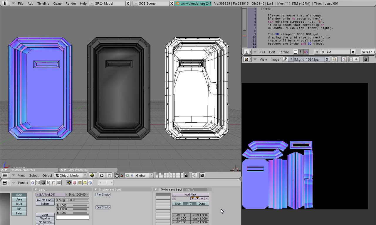
Wire, Solid and Texture view showing both the low (left of each image) and high (right of each image) resolutions meshes made using the same Control Cage (middle) – because the control cage is medium density it is easier to control either way rather than trying to destructive edit the low or high to get either version
Use of a control cage further aids making sure individual surfaces retain as much of their default ‘quadratic’ (four-sided) structure as possible as this makes subsequent ‘sub-division‘ or ‘decimation‘ easier and less likely to cause issues due to the inherent risks that often result from mesh deformation – surface collapse when decimation is used, or pimpling and cracking applying subdivision surfacing for example. Shown below then are the different versions of the same control mesh.
Design note: the high resolution version should use as large a mesh density as possible because Texture Bake relies specifically upon the structure of the object being baked rather than any render based quality settings that might be set for other tools – Subdivision Surfaces (“Subsurf” modifier) for example, allows rendering resolution (“Render Levels:“) to be set independently of Scene (“Levels:“) resolution. In essence the more polygon data there is the better the results (subject to UVW map and texture space availability). If using the “Subsurf” modifier, duplicate the mesh before applying as using “Undo” (“Ctrl+Z“) can occasionally cause issues when reverting to and from a lot of mesh data (mesh detail).

The initial “Control Cage” used as the basis from which both the low and high poly versions of the mesh are made – note that initially the door and rivets in this example are separate to allow for ease of construction; it is not a requirement for meshes be joined into a single object at this point (during construction)

The ‘low-poly’ (low resolution) mesh might typically be a reduced poly count version of the ‘control cage‘ – note that leaving the structure in ‘quads’ tends to facilitate further reduction of the mesh where aggressive optimisation’s are needed (also helps to leave quads in place for re-baking in such instances)

Ideally it’s best to avoid using “Edge Split” either as a modifier or though manual splitting vertices or edges because of the way normals tends to behave – splitting vertices (which is facilitates both types of hard-edge smoothing) changes the orientation of normals which in turn directly affects the baked map. Instead use extra edge loop (sub)divisions placed at strategic points before Subsurface Division is used to control the appearance of ‘hard’ or ‘soft’ edges
")
Once the Control Cage has been prepped with additional edges etc., a “Subsurf” (Subdivision Surface) Modifier can be assigned to increase the objects relative resolution further (x2 iterations shown above for illustrative purposes, x4 for actual rendering)
Clean UVW maps effect render results
Of primary importance to a successful bake is the low-poly objects UVW map so it is critical to make sure it is well laid out, and as clean as is possible, within the space available. This means there should be minimal;
- Vertex/edge/face overlap.
- UVW distortion.
- Broken faces/edges.
- Vertex/edge/face splits.
- Detached groups of faces/islands.
- Tiled, repeat or mirrored areas.
- Inverted faces.
Additionally there should be;
- Adequate border/margin allowance around UV Islands (see below).
This is mainly due the process analysing the individual UV’s of the low-poly mesh and using them as a guide to bake the high resolution meshes normals (akin to painting by numbers). This typically means overlaps, unnecessary splits etc., cause rendering issues, for example the bake process may render the same area multiple times if UV’s overlap resulting in an incorrect Normal map.

The Normal map baked to the area of the available texture and laid out so each element of the object occupies a dedicated area of the texture, no overlaps, distortions or problem areas – note UVW is positioned and sized as if other objects are to use the same texture otherwise is can be mapped to occupy the entire sheet
UV Padding & Margin settings
When unwrapping the UV’s of the low-poly mesh make sure the final layout has a degree of padding around its edges that takes in to account a certain amount of bleed. This is important because, through the use of a “Margin” value in Bake properties, it compensates for the lack of Anti-aliasing when maps are rendered, especially areas with angled or curves borders – without it renders tend to have jagged or stepped edges that cause various issues from the display of black edging to specular or normal map artefacts.
Design note: ‘black’ is not a valid normalised colour so, depending upon the strictness (or sensitivity) of the rendering technology in which the map is used (a game engine for example), may cause issues of differing severity from simple visual artefacts to models appearing entirely black – although it is possible to edit a normal map in an image editor that can still result in non-normalised colours being present so it is preferable to re-render the map to include compensatory allowances.

When looked at closely, the edges around a UV might show severe pixel stepping or jagged edges where the lack of Anti-Aliasing means the bake process cannot fill the gaps; if left in this state it can cause problems in-game or when rendered as part of a texture set because the maps effectively have gaps in them. Activating “Margin” compensates for this but must be allowed for when laying out the UVW map
The amount of padding to allow around the UV’s will vary depending upon the size of the texture itself, and whether there are any secondary considerations to take into account such as “Mipmaps” and “Mipmapping“. Essentially if the UVW map is too compact or gaps between areas too small, it will likely have an adverse effect on usage so enough space needs to be left accordingly – a 512 x 512 texture asset a “Margin:” value of “8”, measured in pixels, might suffice for example. Some trial and error may be required to find an appropriate level of Margin bearing in mind the aforementioned points.
Design note: “Mipmaps” are pre-compiled, reduced resolution, versions of an original texture asset typically employed when “Level of Detail” optimisation’s are being used. In other words, when an object or textured surface is relatively distant from the player/screen there is no need to load in, reduce and then render a full 512 x 512 pixel image. Instead it makes better sense to load a ‘fixed’ (pre-compiled) smaller image, 128 x 128 for example, thereby reducing the amount of real-time computation needed to calculate and re-render the full asset at the smaller size. “Mipmapping” refers to the use of “Mipmaps”. – if the initial UVW is laid out too compactly it may result in area bleed issues on low-level mips due to their small size.

The value used for “Margin” will depend on how much space is available between objects and/or how severe angles and curves are – problems with Anti-Aliasing ‘stepping’ are determined by how steep or curved an edge is, compounded by how much texture space is available for rendering a given area. Some trail and error is typical when trying to determine the correct amount of bleed/margin
Anti-Aliasing, Texture Bake & Normal Maps
The lack of Anti-Aliasing also affects areas within the UV bounds, meaning that lines, edges and detailing suffer the same ‘stepped’ or pixilated artefacting because they too are not being averaged and aliased when baked, a problem that might be not otherwise be as noticeable because it happens within the context of fully normalised neighbouring colours – Aliasing issues around UV borders are more noticeable because black is not a valid normalised colour so gaps, steps or other artefacts are more easily spotted. For example rivets might look blocky at best, or a smudge at worst, because not enough pixels are available to properly define their shape. Similarly, edges and lines cannot be smoothed because they too do not have enough pixel space available to clarify their structure either.

")
The clarity and quality of a Normal map depends heavily on the size of the texture being rendered to and the amount of space dedicated to the object in question – the more space, and the larger the texture, the better the quality. Although some of the negative aspects of Anti-Aliasing can be fixed where larger images have been used, the same is not true for smaller assets because not enough space/data is available
Ideally Aliasing issues should be resolved re-baking texture maps but, as explained above, this is not always possible or practicable. In such instances it may be possible to remedy problems using image editing software by; the use of selectively applied Blur to soften pixels; editing RGB(A) Channels; resizing a larger image.
Design note: when baking textures the images size is determined by the Image slot; to render a 4096×4096 Normal map the Image slot needs to contain a placeholder the same size (this can be an actual bitmap image or a “Generated” image dataBlock – made real when saved).
")
blur and sharpen: often used on photographs to remove slight pixelation, noise or moiré, an image is given a low ‘blur’ value (less than “1%“) to soften the visible edges of pixels and then sharpened to re-establish edges and lines otherwise lost in blurring

RGB Channel editing: individual RGB(A) image Channels can be edited directly or by temporarily splitting them into sub-components (revealing the 8 bit 256 grey-scale layer) that can then be corrected by painting out problem areas before being recombined

Re-size larger image: the original normal map is rendered out at least twice actual size and then re-scaled as needed relying then on the image editors automated Anti-Aliasing pixels to create smoother results – of the three techniques this is the most straightforward (but not always the best)
Each of the above approaches have their respective ‘Pros and Cons’ but common to all is the necessity for images to be re-normalised after editing to make sure they only contain valid ‘normalised’ colours – done manually in an image editor it may be necessary to fill any ‘dead’ (black) space with a generic normalised colour tone; RGB: 127, 127, 255 before then properly re-normalising the image to make sure no invalid colours remain.

Manually editing a Normal map to remove any obviously invalid colour, in this instance the black areas from the original rendered image, which can then be properly filtered and re-normalised
")
Re-normalising a Normal map in nJob. Aberrant and incorrect values can be converted into valid ‘normalised’ RGB colour using the “Smooth out Gaps” option from the “Filter” menu which averages colour transitions
Fixing normals maps isn’t an absolute necessity, i.e. using the images as they come out of the bake process isn’t going to ‘break’ anything, all it means is that certain types of detail will appear misshapen or missing (thin lines and small features like rivets, screws and scratches in particular). If you do want to fix the normal map errors, rather than fix everything, it’s best to initially fix only those details that will be immediately visible to the end user. Prioritise what needs to be corrected.
Mirrored UVW’s
A common optimisation for certain types of game object is to make use of “mesh mirroring“; an object is made, mapped and textured as normal, then split in two, one half deleted, the other duplicated and mirrored to replace the side removed. The result is a complete model less 50% of the originals texture space and UVW map. However, there is a problem with this approach where the mesh is normal mapped because the colours are representative of structure that have very specific, fixed orientations. In other words, mirroring a mesh will not correctly mirror a normal map, with the result that half the object will appear inverted. Shown below for example, if the model is mirrored so the blue-biased right side is duplicated over to the left (discarding the original pink-biased left side) it can result in the game engine reading the normal map as if the blue-biased sections are still on the right, causing that half of the model to appear inverted when mirrored over to the left.
Design note: this problem occurs irrespective as to whether the mesh has had “Apply” set.

Looking closely at the image (highlighted UV sections are removed) there are noticeable differences between ‘left’, ‘right’, ‘up’ and ‘down’ and how normalised colours relate to those orientations – the left side of the mesh is pink-biased, the right is blue-biased. This can be problematic for mirrored objects because normals are essentially facing the wrong way, or rather they pertain to the object as it was originally, when sections are mirrored or their orientations are changed

A mirrored mesh is a common optimisation for game models whereby one half of the mesh is deleted, the remainder is then duplicated and flipped to replace the removed section resulting in a complete object using fewer resources
An optimisation technique that ordinarily works for typical game models becomes problematic when using mirrored meshes because normals represent specific structural detailing – mirroring a mesh doe not mirror normals, it inverts them because they retain their original orientation
The fix for inverted normals in this situation is usually done though specific game engine coding that inspects an asset once it loads to see if it’s mirrored; if it is the associated normals are flipped appropriately, correcting the problem. This being the case however, when making the model, both sides of the mesh still need to be baked to ensure correct normalisation and to avoid inadvertent splits and divisions in the resulting map. This obviously means the section of the mesh to be discarded needs to be present as part of the objects over UV mapping, but as it’s presence is only important to ensure proper normalisation, it can be scaled down in size and placed in any available, unused or unassigned space.
Design note: only the side being kept needs to be properly UVW unwrapped, the side to be discarded can be roughly mapped enough to ensure the Normals can be baked properly.

Even though the mesh is to be mirrored, be sure to bake the map against a complete model to prevent the inadvertent introduction of hard lines where the mesh is to be split apart and mirrored – normals need to properly average across the centre-line else a hard line will appear there (indicative of a ‘smoothing’ line)
Mesh Smoothing & Normal Maps
Although not explicitly a problem associated with mirroring meshes, breaks in surface continuity that might result from two halves of an object being joined, edges being marked as “Sharp” or “Split“, “UV Seams“, anything in fact that breaks the mesh into individualised elements or sub-elements, can have unwanted effects on the way normals are displayed.
The easiest way to understand the problem is to think about the way mesh smoothing typically works. When smoothing is assigned to a mesh via the “Set Smooth” property (“Editing” buttons, “Link and Materials” properties panel), the same global value is initially applied to all surfaces; everything is treated as if its part of the same larger group. The result of this is surface shading, the way the model reacts to a Scenes generic illumination, being averaged across the entire mesh, making it appear to be a uniformly surfaced and shaded Object. If an edge is subsequently marked “Sharp“, so as to create a “Smooth Group“, it ‘breaks’ this uniformity because vertices along such edges are physically split apart, one for each sub-element on either side of what is now a well defined (‘hard’) line.
 versus Split vertex-normals")
When vertices are split using the Edge Split Modifier, as a result of UV layout, or other reason, the associated normals tends to point in slightly different directions – a single vertex shared between neighbouring faces points in an ‘averaged’ direction; split vertices point in more independent orientations. This means shading and other surface properties are no longer ‘shared’ or ‘averaged’ across neighbouring elements resulting in a hard line appearing. This division is also baked into Normal maps
What makes this problematic for normal maps is that in breaking the mesh, the way normals are now pointing is individualised – their orientation to what were joined neighbours has changed, and in doing so the relationship with corresponding sections of the high-resolution mesh has also changed. When ‘smoothing’ is generally done to the high-resolution mesh through the management of structure and detailing, splitting edges as explained above, i.e. applied to the low-poly mesh, is akin to marking an already sharp edge as a sharp edge. Shown below for example, is the difference between normals baked to the same low-poly mesh with (top) and without (bottom) the “Edge Split” Modifier assigned (creating effective “Smooth Groups“), note the appearance of lines in the bake with split edges (top). To avoid this happening, where-ever possible rely on the high-resolution mesh for ‘smoothing’.
Design note: it is important to understand that Normal maps are not splitting the mesh in any way to achieve smoothing. Instead it’s done at the pixel level based on Normal map colouration – each pixel represents structure, which might also related to the ‘smoothed’ edge when rendered, thus in effect over-riding the need to employ edge splits (certainly to a greater extent – there are still some situations where they are needed).

When a Normal map is baked to a version of the mesh marked with “Sharp” edges, hard lines appear in the map where-ever those edges occur – this happens because surface continuity is broken as a result of having to physically split vertices on such edges; hard and soft edges/surfaces are physical attributes – hard edges appear because vertices at a given point are split into corresponding groupings that only share surface properties with their immediate and conjoined neighbours (which from a “Smoothing Group”)
")
Generally speaking when baking Normal maps it preferable to disable or remove any edges marked as Sharp as ‘smoothing’ is determined by the physical attributes of the high-resolution mesh and baked appropriately into the Normal map – leaving edge splits in place compounds the problem and in affect adds a sharp edge (edge marked sharp on the low-poly) on top of a sharp edge (structural detailing read from the high-poly mesh)
Image Format & Lossy Compression (avoid JPG)
When saving or working with Normal maps once they have been baked and are ready for use, it is generally preferable to use an image format that supportive raw data, or uses loss-less compression. This is important to make sure that colour data remains fully normalised else, when used in game, surfaces to which assets are applied will exhibit various visual problems, from black spots to pixelation to blockiness and other artefacts caused by the presence of non-normalised colours and/or compression artefacts. The following tend to yield good results; TGA, BMP, PNG, BMP, DDS*, TIF. And especially avoid JPG and other types of lossy image format.
Design note: *when using DDS be sure to select the right sub-format, there are several available depending upon what’s being compressed, choose the wrong one for Normal maps and it can cause as many problems as using JPG. DXT5 is typical.

Taking into account the image above being a JPG, the left side shows the raw Normal maps without compression artefacts because it was saved as a TGA image. On the right some relatively severe pixelation and spotting is visible that will cause visual artefacts in-game. This is typical using JPG and even a small amount of compression so it’s best to avoid using the format altogether where Normal maps are concerned
Conclusions; texture space and relative sizes
Working with normal maps present all sorts of challenges, some not directly related to the texture maps themselves, pixelation and resolution related issues for example, as a result of the amount of texture space available for use. Typically issues of this nature are solved by simply increasing the UVW map. However, before doing this keep the following two points in mind; UVW maps and texture resolution should be ‘relative’ across assets, i.e. avoid increasing UV map size for the same of gaining more resolution if in doing to the result makes the model stand out as being too well defined relative to its surroundings; to save space and reduce load times share texture sheets as much as possible, which means having to think ahead a little with respect to asset organisation – what goes where.
These may not seem particularly important considerations, certainly not whilst working on individual assets. However, at a project level, and when creating content for games in particular, assets are rarely used in isolation, which means making sure small objects don’t use disproportionately large amounts of texture space, especially where such items are likely to only be seen at a distance. So, despite the need to use as much space as is possible to bake clean, clear Normal maps, doing so should be (needs to be) limited by practical concerns and further considered within the context of assets being used on a model placed in a room, located in a scene in a much larger overall game world.

